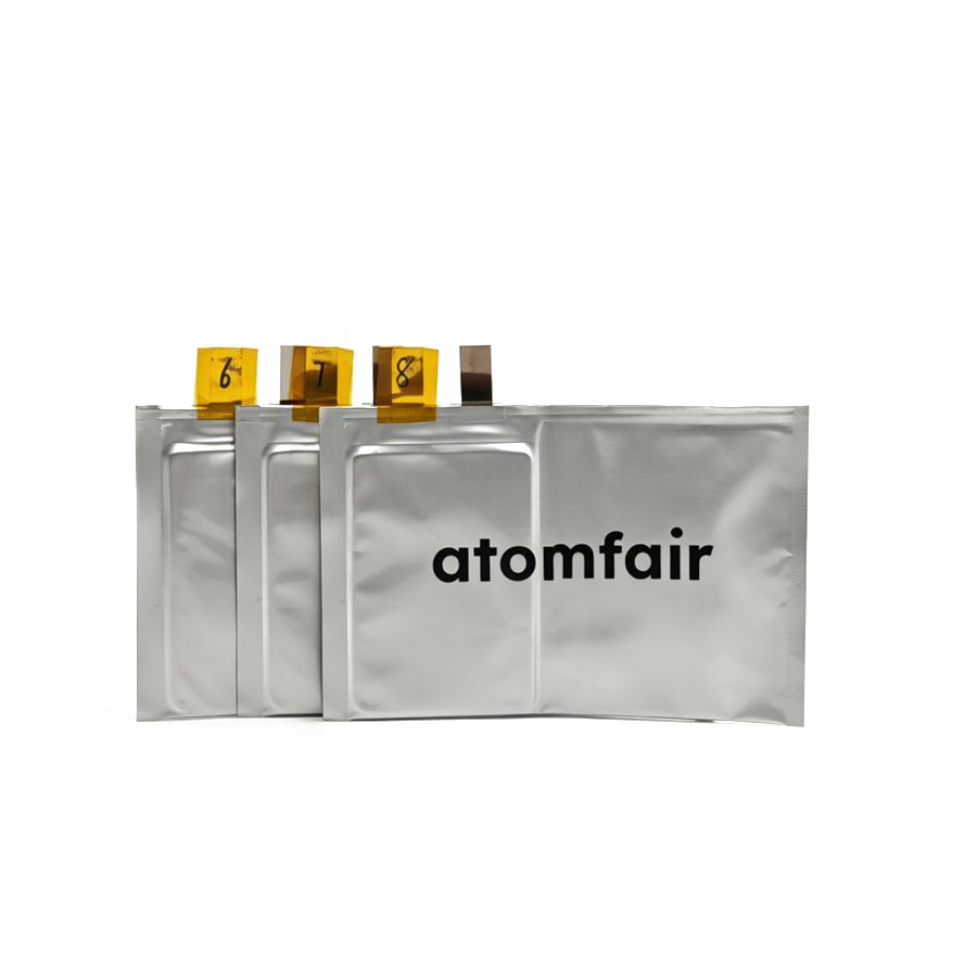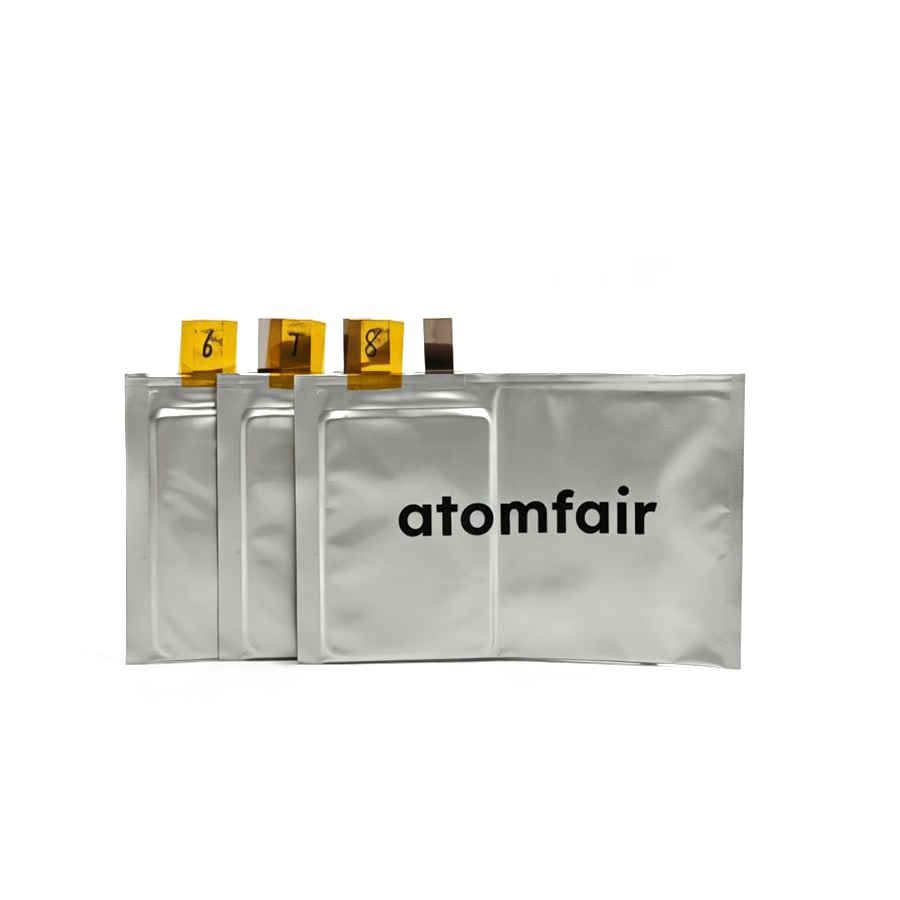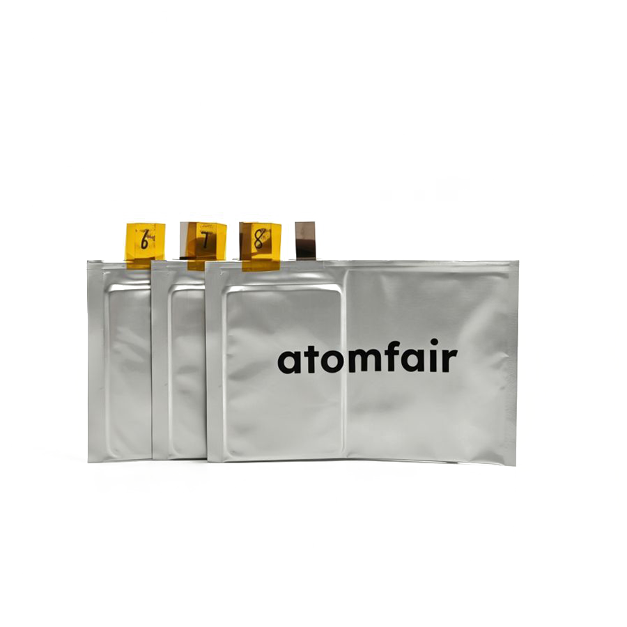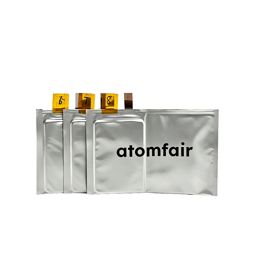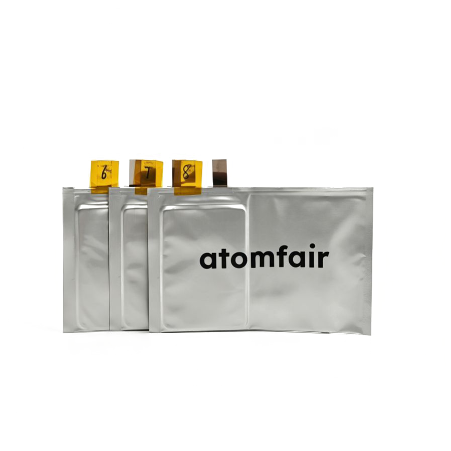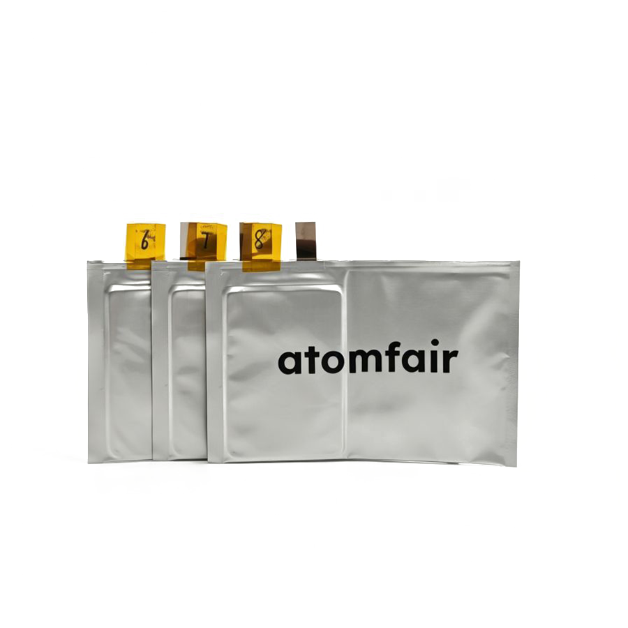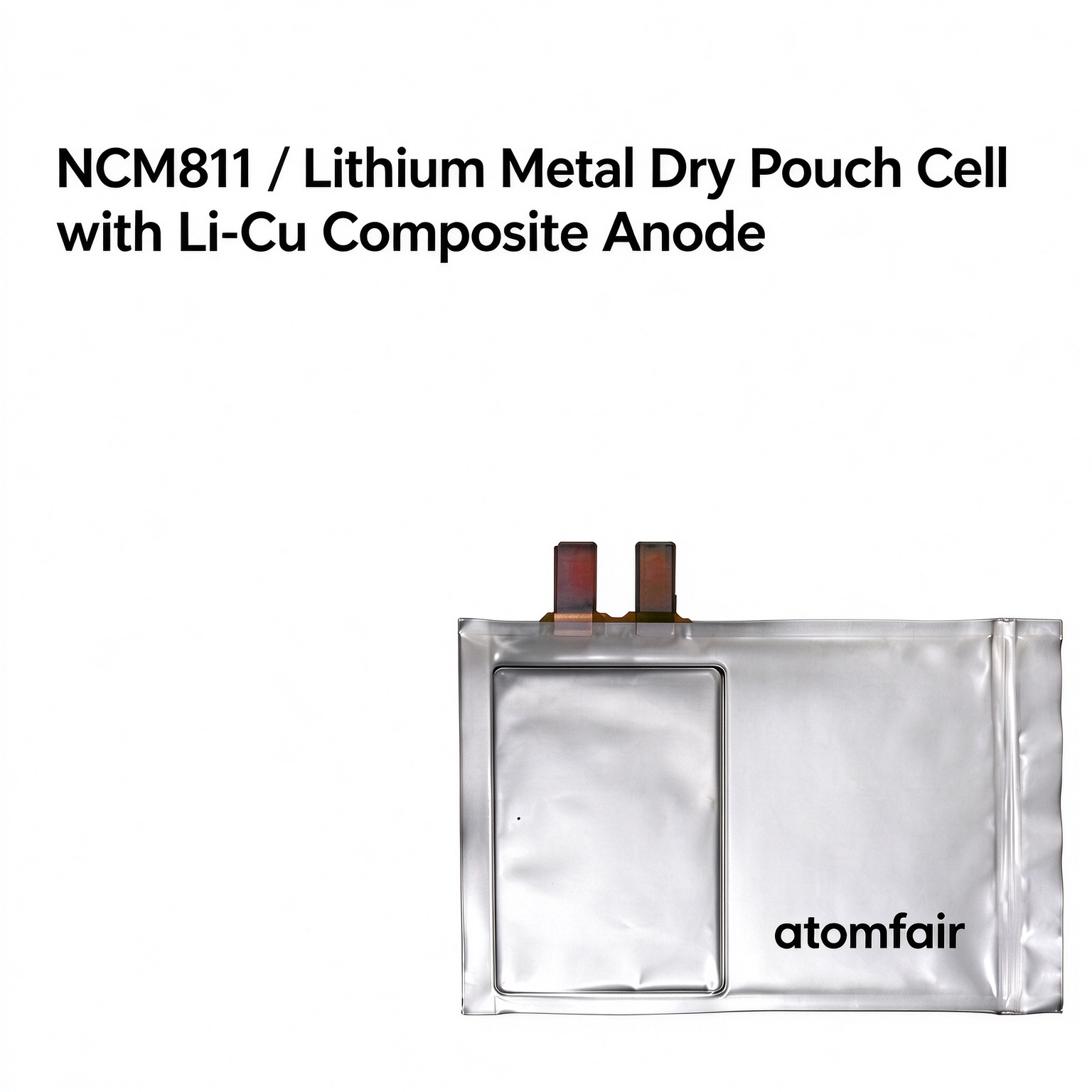
| Product Name: NCM811 Dry Pouch Cell (0.3 Ah) |
Cell Type: Lithium Metal Pouch (Unfilled) |
Product Code (SKU):AF-BM-C-81LC-03A0-0AF8 |
Assembly Environment: Dew Point ≤ -40 °C Cleanroom |
1. Scientific Overview & Research Benchmark Value
The ATOMFAIR® 0.3 Ah (300 mAh) NCM811 / Li-Cu Dry Pouch Cell is supplied fully stacked and tab-welded in an electrolyte-free (unfilled) state. In modern battery materials research, transitioning from coin cells (CR2032) to pouch cells is essential for validating practical electrochemical performance. While standard coin cells typically use thick lithium discs (>250 μm, N/P > 10) and heavily flooded electrolyte (E/C > 15–50 g/Ah) that mask continuous solvent depletion and dendritic failure, a standardized single-layer dry pouch cell exposes true interfacial kinetics.
This 1/2-layer configuration couples a high-loading single-crystal Ni83 (product designation: NCM811) cathode with an ultrathin 20+6+20 μm Li-Cu composite anode at an engineered areal N/P ratio of ~0.80, separated by a 12 μm PE + 2 μm Al₂O₃ ceramic-coated membrane. Supplied without liquid electrolyte, the dry core enables researchers to inject custom electrolyte formulations (such as localized high-concentration electrolytes [LHCE], fluorinated ethers, ionic liquids, or functional film-forming additives) to investigate wetting behavior, solid electrolyte interphase (SEI) evolution, gassing dynamics, and cathode-electrolyte interphase (CEI) impedance without pre-existing solvent interference.
Key Research Objective: Provide a reproducible, documented pouch-cell testbed operating across a 3.0 V to 4.3 V full-cell voltage window to benchmark novel liquid or quasi-solid electrolytes, study stack-pressure-coupled lithium plating/stripping, and track Coulombic efficiency under controlled lithium and electrolyte inventories.
2. Electrode Stack Architecture & Dimensional Schematics
To support electro-chemo-mechanical modeling and post-mortem analysis, all coating loadings and electrode geometries of this dry pouch cell are strictly documented below alongside physical photographs and dimensional schematics.

Physical Cell Structure (Tab View)
Ultrasonic-welded positive aluminum tab and negative nickel tab protected by heat-sealable polypropylene (PP) tab film.
|

Pouch Enclosure & Gas Pocket
Aluminum laminate pouch enclosure featuring an extended lateral gas pocket for electrolyte injection and formation degassing.
|

Cross-Sectional Layer Structure
Microscopic layer allocation detailing the 1/2 stacking structure, double-sided SC-Ni83 cathode, 12+2 μm ceramic separator, and 20+6+20 μm Li-Cu anode.
|

Electrode Overhang & Geometry
Portrait electrode core (Width 46.5 mm < Length 65.0 mm) with engineered 0.5 mm perimeter overhang margin and lateral gas pocket.
|
3. Verified Engineering Specifications & Derived Metrics
All parameters below are verified against Atomfair batch specifications and first-principles electrochemical calculations. Batch-specific mechanical dimensions not listed in the public datasheet are marked with placeholders for QC verification.
3.1 General Cell Architecture
| Parameter | Verified Specification | Source / Basis |
|---|---|---|
| Nominal Capacity | 0.3 Ah (300 mAh) | Original Atomfair Specification |
| Operating Voltage Window | 3.0 V to 4.3 V (Full-Cell Terminal Voltage) | Original Atomfair Specification |
| Lamination Structure | 1/2 Stacking Layers (1 double-sided cathode / 2 Li-Cu anode faces) | Original Atomfair Specification |
| Assembly Environment | Dew Point ≤ -40 °C Cleanroom (Pre-filling moisture baseline ≤ 200 ppm) | Original Atomfair Specification |
| Enclosure Format | Aluminum Laminated Pouch Film with Integrated Lateral Gas Pocket | Original Atomfair Specification |
| Dry Cell Net Weight | 6.08g | Batch Packaging QC Record |
3.2 Positive Electrode (Cathode) Parameters
| Parameter | Verified Value | Source / Calculation Basis |
|---|---|---|
| Active Cathode Material | Single-Crystal Ni83 (Product Designation: NCM811) | Original Atomfair Specification |
| Active Material Weight Fraction | 97.4 wt% | Original Atomfair Specification |
| Material Specific Capacity | 220 mAh/g (0.1C half-cell reference) | Original Atomfair Specification |
| Coating Areal Density | 24 mg/cm² (single-sided basis) | Original Atomfair Specification |
| Compacted Density | 3.4 g/cm³ | Original Atomfair Specification |
| Effective Areal Capacity | ~5.14 mAh/cm² per side (~10.29 mAh/cm² double-sided) | Calculated: 24 mg/cm² × 97.4% × 0.220 mAh/mg |
| Cathode Sheet Dimensions | 45.5 mm (W) × 64.0 mm (L) (Active Area: 29.12 cm² per side) | Original Atomfair Specification |
| Calculated Cathode Capacity | ~149.8 mAh per side (~300 mAh total double-sided) | Calculated: 29.12 cm² × 5.143 mAh/cm² |
| Positive Tab Specification | Ultrasonic-Welded Aluminum (Al) Tab | Original Spec + Batch Drawing |
3.3 Negative Electrode (Anode) & Separator Parameters
| Parameter | Verified Value | Source / Calculation Basis |
|---|---|---|
| Anode Architecture | Ultrathin Lithium Foil Cladded on Copper Substrate (Li-Cu Composite) | Original Atomfair Specification |
| Composite Thickness Profile | 20 μm Li + 6 μm Cu + 20 μm Li (Total: 46 μm) | Original Atomfair Specification |
| Theoretical Lithium Areal Capacity | ~4.12 mAh/cm² per 20 μm metallic Li side | Calculated: 20 μm × 0.534 g/cm³ × 3860 mAh/g |
| Engineered N/P Ratio | ~0.80 (Areal Basis) (4.122 ÷ 5.143 mAh/cm²; ~0.83 total capacity basis with overhang) | Derived from Verified Stack Specs |
| Anode Sheet Dimensions | 46.5 mm (W) × 65.0 mm (L) (Area: 30.23 cm²; 0.5 mm overhang per edge) | Original Atomfair Specification |
| Negative Tab Specification | Nickel (Ni) Tab with Polypropylene (PP) Sealant Film | Original Atomfair Specification |
| Separator Membrane | 12 μm Polyethylene (PE) Base + 2 μm Al₂O₃ Ceramic Coating (14 μm total) | Original Atomfair Specification |
| Target Electrolyte-to-Capacity (E/C) Ratio | Lean-Electrolyte Benchmark: ≤ 1.5 – 2.0 g/Ah (~0.45 – 0.60 g / ~380 – 500 μL active core dosing) Baseline Screening Injection: 0.4 – 0.8 mL (~0.5 – 1.0 g gross injection including gas-pocket wetting allowance) |
Lithium-Metal Pouch Protocol (Battery500 Benchmark) |
| Core Pore Volume & Syringe Dosing Note | Total active core pore volume is ~135 μL (cathode ~115 μL + separator ~18 μL; dense Li-Cu anode has 0% internal porosity). Dosing above core volume fills perimeter and lateral gas pocket. Calibrate syringe injection according to lean-electrolyte kinetics (≤ 2.0 g/Ah) or flooded formulation screening. | Core Pore Volume First-Principles Calculation |
4. Recommended Glovebox Electrolyte Injection, Wetting & Formation Protocol
Metallic lithium (20 μm surface cladding) reacts rapidly with trace moisture above 5 ppm H₂O. Unpack and process the cell strictly inside an Argon-filled glovebox (H₂O, O₂ < 1 ppm). Below is the baseline activation protocol with engineering notes on electrolyte dosing and stack pressure scaling for lithium-metal pouch cells.
| Experimental Step | Standard Operating Procedure | Target Operating Metric | Compatible Hardware & Engineering Notes |
|---|---|---|---|
| Step 0: Coin-Cell Pre-Screening (Optional) | Before committing pouch cells, assemble Li-Cu || Li-Cu symmetric coin cells (to evaluate overpotential) or NCM811 || Li-Cu coin cells to verify electrolyte compatibility. | Plating/stripping at 0.5–2.0 mA/cm²; check initial CE & SEI impedance | Matching anode foil for coin-cell punching: Lithium Copper Laminated Foil 10x10cm Battery-Grade |
| Step 1: Glovebox Dosing & Vacuum Pre-Seal | Unpack dry cell in Argon glovebox (H₂O, O₂ < 1 ppm). Dispense electrolyte via precision pipette/syringe into the open gas-pocket edge, then vacuum pre-seal inside a glovebox vacuum standing sealer. | Lean E/C Benchmark: ≤ 1.5–2.0 g/Ah (~0.45–0.60 g / ~380–500 μL net in stack). Baseline Screening Injection: 0.4–0.8 mL (~0.5–1.0 g) depending on solvent density. Pre-Seal Vacuum: ≤ -95 kPa |
Compatible with custom LHCEs, fluorinated ethers (e.g., LiFSI in DME/TTE), or carbonate/ester formulations. Contact inquiry@atomfair.com if custom pre-formulated lithium-metal electrolytes are required. |
| Step 2: Wetting & Stack Pressure Setup | Clamp the active cell body (area: 30.23 cm²) between flat compression plates to ensure uniform electrode-separator contact and avoid dead-volume entrapment. | Wetting Temperature & Duration: 25 °C (ambient glovebox) for 12–24 h. *Lithium-Metal Note: Ambient 25 °C is recommended over elevated 45 °C to prevent parasitic chemical corrosion on 20 μm Li foil. Wetting Contact Pressure: 0.10 – 0.20 MPa (~31 – 61 kgf total force on 30.23 cm²). |
Compatible fixtures (calibrated for 30.23 cm² cell area): • PP Pouch Cell Test Fixture 150kg (0–0.49 MPa range; ideal for wetting & up to 0.40 MPa cycling) • 6061-T6 Fixture 250kg (0–0.81 MPa range; ideal for 0.35–0.70 MPa Li-metal high pressure) |
| Step 3: Stepwise Low-Rate Formation | Maintain uniaxial stack pressure on battery cycler: (1) Charge at 0.05C (~15 mA) CC to 3.5 V or for 2.0 h; Rest 10 min. (2) Charge at 0.1C (~30 mA) CC-CV to 4.3 V (0.02C / 6 mA cutoff); Rest 10 min. (3) Discharge at 0.1C (~30 mA) CC to 3.0 V. |
Voltage Window: 3.0 V – 4.3 V Cycling Stack Pressure: 0.35 – 0.50 MPa (~108 – 154 kgf total force on 30.23 cm²) (operational window: 0.30 – 0.70 MPa / 91 – 216 kgf). *Lithium-Metal Rule: Unlike graphite anodes (0.05–0.1 MPa), lithium-metal pouch cells require ≥ 0.35 MPa (350 kPa) to suppress dendritic mossy growth and maintain interfacial contact. |
Optimal stack pressure is electrolyte-dependent (literature benchmarks span 0.35–0.70 MPa for Li-metal pouch cells). Adjust fixture torque to match your target MPa. |
| Step 4: Vacuum Degassing & Final Seal | Return cell to Argon glovebox. Puncture the lateral gas pocket under vacuum to evacuate initial SEI/CEI formation gases, execute the final hermetic seal along the inner pouch margin, and trim off the sacrificial gas pocket. | Vacuum degas & final seal; Rest at 25 °C for 24 h prior to long-term cycling | Requires a glovebox vacuum degassing sealer. For auxiliary top/side foil thermal sealing or post-trim reinforcement, see ATOMFAIR® 300mm Pouch Cell Heat Sealer (HPF729). |
5. Related Unfilled Dry Pouch Cell Selection Matrix
Compare verified ATOMFAIR® dry pouch cell architectures across single-crystal high-nickel, high-voltage lithium cobalt oxide, lithium iron phosphate, and lithium-rich manganese chemistries:
| Product Model & Direct Catalog Link | Cathode / Anode Chemistry | Capacity / Stack Layers | Target Research Application |
|---|---|---|---|
| NCM811 / Li-Cu Composite Dry Pouch Cell (Current Product) | Single-Crystal Ni83 / 20+6+20 μm Li-Cu | 0.3 Ah (1/2 Layers, 3.0–4.3 V) | Electrolyte screening, CE quantification & Li-metal interface kinetics |
| HV-LCO Dry Pouch Cell – Lithium Metal Anode (1.3 Ah) | High-Voltage LCO / Metallic Lithium | 1.3 Ah | High-voltage CEI film stability & oxidative electrolyte screening |
| LCO Dry Pouch Cell (6.5 Ah, 4.45 V) – Si/C Anode | 4.45 V LCO / Silicon-Carbon (Si/C) | 6.5 Ah (Multi-Layer) | High-capacity silicon-anode swelling stress & binder/additive validation |
| LFP Dry Pouch Cell – Lithium Metal Anode (1.1 Ah) | LFP / Metallic Lithium Anode | 1.1 Ah | Flat-plateau anode SEI study & lithium plating/stripping isolation |
| LFP Dry Pouch Cell (1.1 Ah, 14/15 Layers) – Li-Cu Anode | LFP / Li-Cu Composite Foil | 1.1 Ah (14/15 Layers) | Multi-layer stack uniformity & long-cycle Li-Cu interface evaluation |
| LMR Dry Pouch Cell (1.0 Ah, 11 Layers) – Graphite Anode | Li-Rich Manganese (LMR) / Graphite | 1.0 Ah (11 Layers) | Anionic oxygen redox activation, voltage fade & gassing suppression |
| LMR Dry Pouch Cell (6.2 Ah, 14/15 Layers) – Li-Cu Anode | Li-Rich Manganese (LMR) / 20+6+20 μm Li-Cu | 6.2 Ah (14/15 Layers, 2.0–4.8 V) | High-energy (>400 Wh/kg class) multi-layer pouch cell prototyping |
Browse all unfilled cells: Complete Dry Pouch Cell Category Hub | Need custom specifications? Custom Cell Engineering Services
6. Academic Citation, Glovebox Storage & Handling Precautions
When referencing this standardized dry pouch cell platform in academic manuscripts or technical reports, please use the following citation format:
Atomfair LLC. (2026). NCM811 / Lithium Metal Dry Pouch Cell with Li-Cu Composite Anode (0.3 Ah; SKU: AF-BM-C-81LC-03A0-0AF8). Atomfair Scientific Materials Catalog. https://atomfair.com/product/ncm811-dry-pouch-cell-0-3ah/Atmospheric Exposure & Storage Constraints
Inert Storage Requirement: Unfilled dry pouch cells must remain sealed inside their vacuum moisture-barrier bags until immediately prior to electrolyte dosing, or be stored inside an Argon glovebox / dry room (dew point ≤ -40 °C). The 20 μm metallic lithium cladding on the Li-Cu anode reacts vigorously with atmospheric moisture above 5 ppm H₂O. Do not short-circuit, bend, puncture, or expose the dry core to temperatures above 60 °C.
Engineering Customization
Atomfair supports custom pouch cell batch fabrication: customize nominal capacity (0.1 Ah to 10 Ah), stack layer counts, tab overhang geometry, and separator coatings to match your laboratory testing protocols.
Every advanced material, component, equipment, and instrument in our catalog is backed by rigorous testing. We maintain strict internal quality management frameworks and align with CE conformity metrics to deliver transparent, reproducible performance data via our public open-science repository.
To request raw batch performance data, submit formal vendor registration paperwork, or execute a fast-turnaround R&D manufacturing loop, contact us at inquiry@atomfair.com.
Item is dispatched under the Atomfair Shipping & Delivery Framework (Free worldwide shipping on orders over $59 USD excl. heavy equipment). Return is governed by the Atomfair Return & Refund Policy (7-day technical return window).