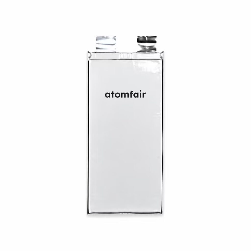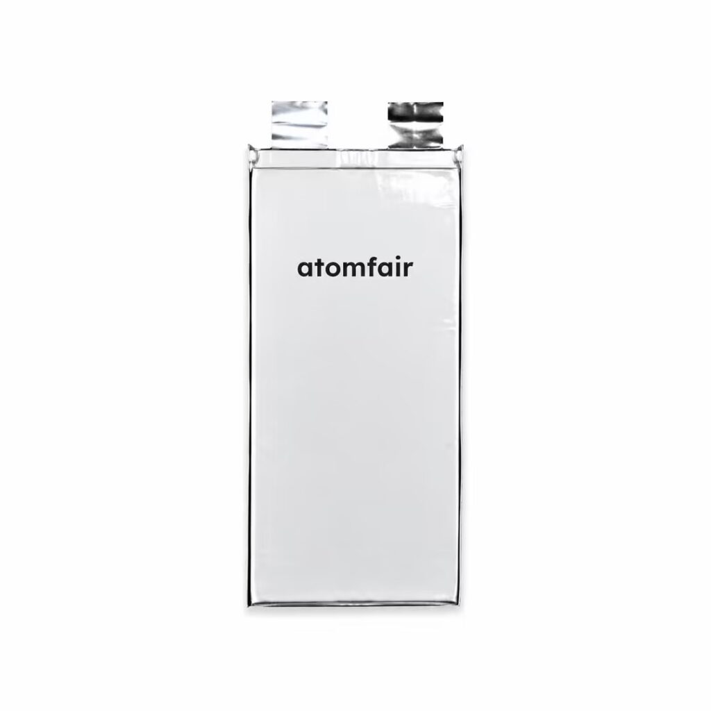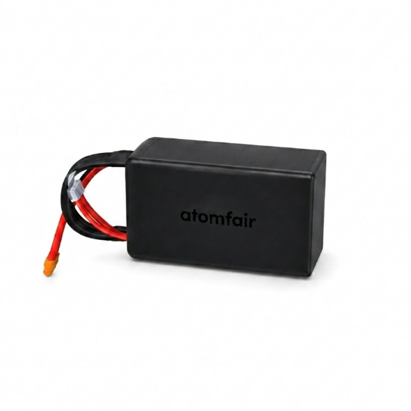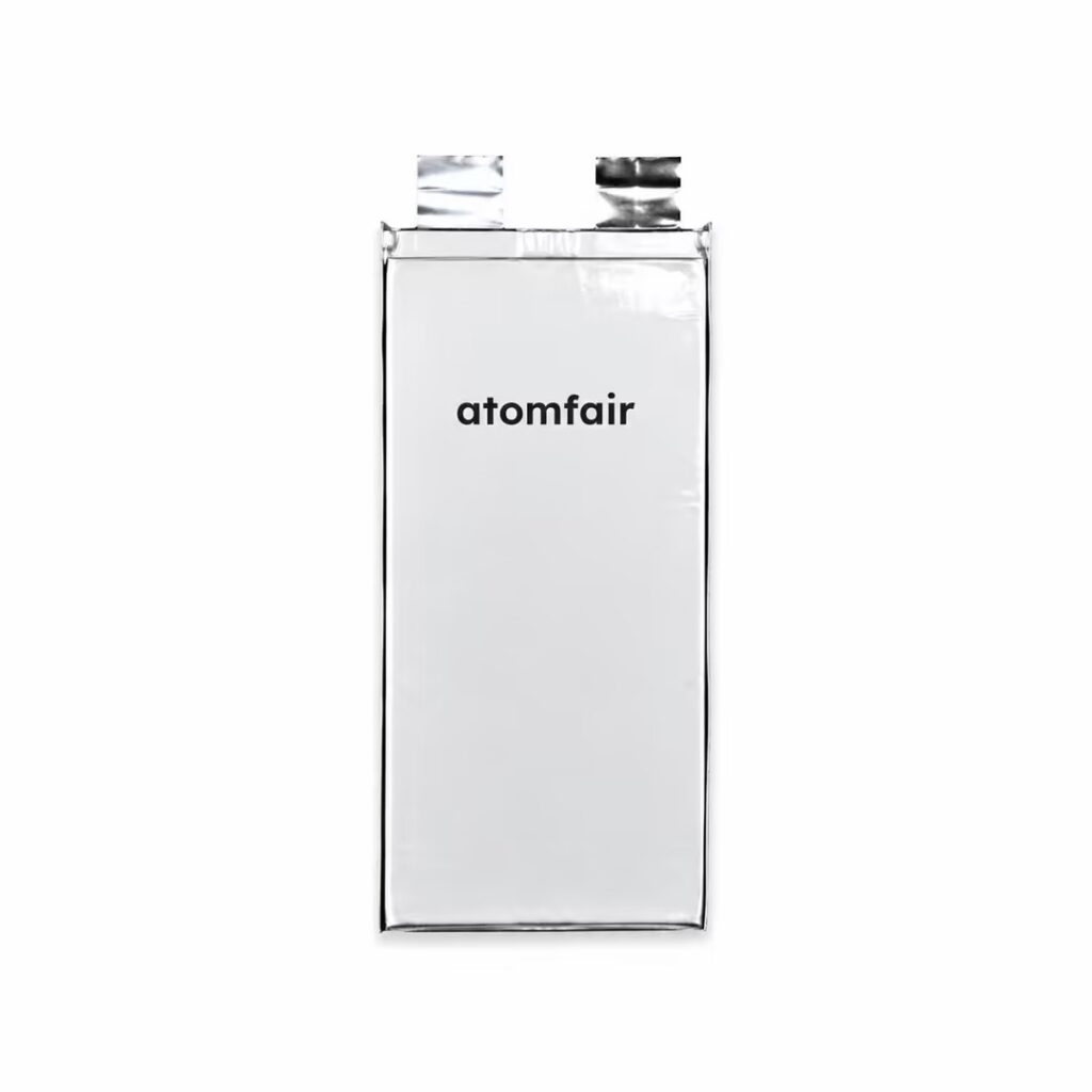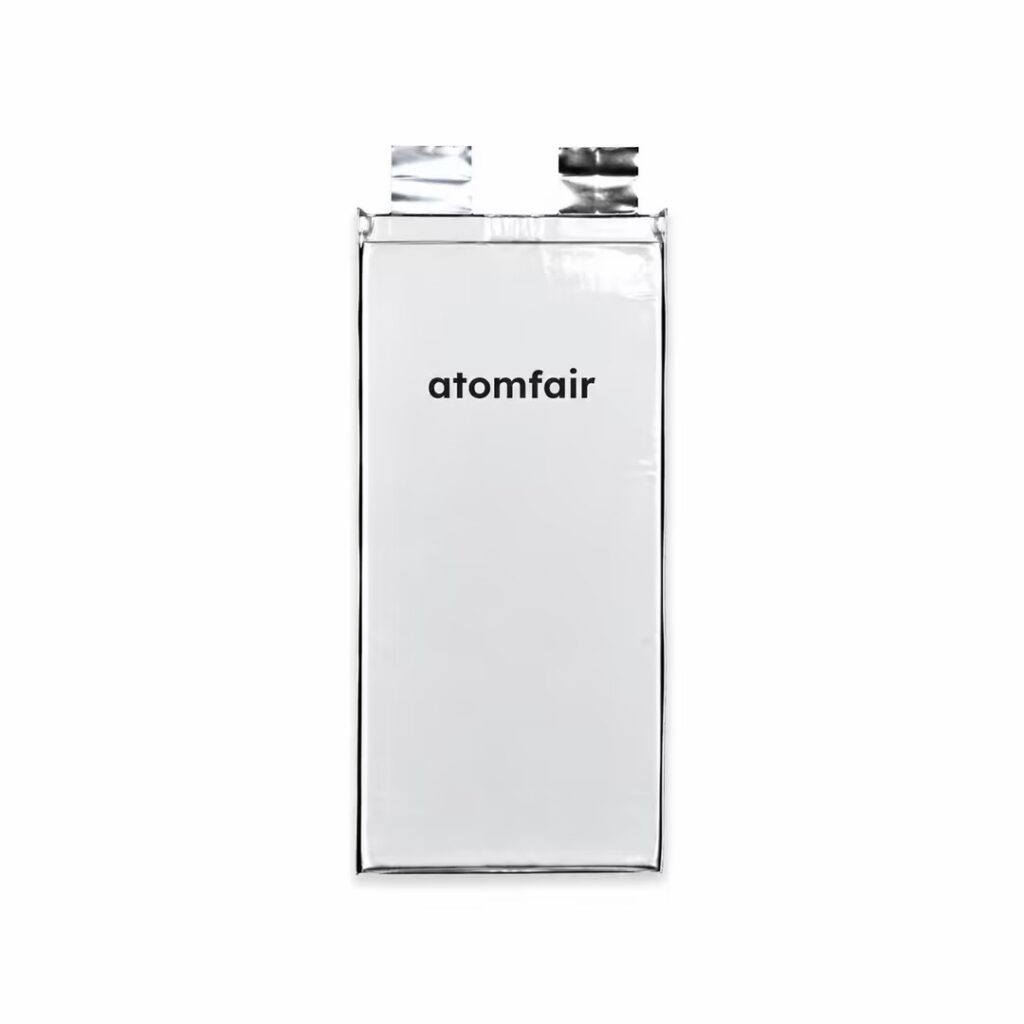
HP Series HPEG / HPED Solid-State Cells (Balanced Power Series) | ATOMFAIRCOMMERCIAL GRADE · PRODUCTION
|
|||||||||||||||||||||||||||||||
|
|||||||||||||||||||||||||||||||
|
TAILORED SOLUTIONS FOR RESEARCH
Contact our engineering team for technical support or official institutional quotations.
EMAIL: INQUIRY@ATOMFAIR.COM
|
|||||||||||||||||||||||||||||||
|
MANUFACTURER: ATOMFAIR LLC
BRAND: ATOMFAIR®
|
|||||||||||||||||||||||||||||||
The HPEG/HPED solid-state cells require stable external multi-point clamping forces to maintain uniform contact boundaries across active internal layers. Over-discharge must be prevented by ensuring terminal voltage does not drop below the specified low potential floors.
- Compression Fixture Requirement: The cell must be housed within a rigid compression fixture plate to maintain uniform contact across internal layers.
- Over-Discharge Prevention: Terminal voltage must not drop below the specified low potential floors to prevent damage.
- Certified Charge/Discharge Compliance: Charge and discharge operations must follow certified parameters to ensure safe and reliable performance.
Secure the cell in a compression fixture before electrical connection. Then connect to a charge/discharge system following certified parameters and monitor voltage to prevent over-discharge.
Required Equipment: Rigid compression fixture plate
- Secure the cell in a compression fixture
House the individual cell array securely within a rigid compression fixture plate structure to ensure uniform contact. - Connect to charge/discharge system
Connect the cell to a charge/discharge system and follow certified charge/discharge parameters for the specific variation. - Monitor voltage to prevent over-discharge
Prevent terminal contact strings from dropping below specified low potential floors by monitoring voltage during operation.
What is the cycle life of the HPEG/HPED solid-state cell under the specified 10C continuous discharge, and how does the test condition of 1C charge/8C discharge relate to real-world high-rate operation?
The HPEG and HPED solid-state cells achieve a verified lifecycle of ≥600 cycles when tested under a 1C charge / 8C discharge loop protocol. While the continuous discharge rating is 10C, the cycle life validation uses a slightly lower 8C discharge to mimic sustained high-rate stress without exceeding the cell's thermal or mechanical limits. This ensures the 22Ah pouch delivers reliable long-term performance in demanding UAV applications where continuous 10C bursts are required intermittently.
What external compression fixture is required to maintain proper internal contact and prevent performance degradation in these solid-state pouch cells?
These solid-state pouch cells require stable external multi-point clamping forces to maintain uniform contact boundaries across active internal layers. The operational compliance notice explicitly states that individual cell arrays must be housed securely within a rigid compression fixture plate structure. Without proper fixturing, anisotropic crystal volume expansion cracks can occur, compromising the 10C continuous discharge capability and the ≤40°C thermal rise management.
How does the ≤40°C surface thermal rise under continuous 10C discharge affect integration with sensitive avionics in UAV platforms?
The solid-state architecture caps surface thermal rise strictly beneath 40°C peak increment under continuous 10C output, which is intentionally designed to safeguard sensitive adjacent avionic systems from heat damage. This thermal mitigation is achieved through deep phase stability that prevents anisotropic crystal volume expansion, allowing the 22Ah pouch to be mounted in close proximity to flight controllers, GPS modules, and cameras without requiring active cooling or large thermal standoffs in most commercial UAV layouts.
The HPEG/HPED solid-state cell series (22Ah, 10C continuous discharge) delivers a balanced compromise between high-rate current extraction and extended cycle life, with surface thermal rise capped at 40°C to protect adjacent avionics in demanding UAV propulsion stacks.
Positive
- Elite thermal mitigation for avionics: Cell face surface rise is restricted to ≤40°C under continuous 10C discharge, protecting sensitive adjacent electronic systems during high-load operation.
- Extended sintering lifetime: Achieves ≥600 cycles under 1C charge/8C discharge validation protocols, reducing total fleet operating costs for commercial UAV operators.
Trade-offs
- Requires compression fixture mounting: Solid-state high-drain pouch cells demand stable external multi-point clamping forces within a rigid compression fixture to maintain uniform contact across internal layers.
- Strict low-voltage cutoff compliance: Terminal contact strings must not drop below specified low potential floors to prevent damage; certified charge/discharge parameters must be followed.
Every advanced material, component, equipment, and instrument in our catalog is backed by rigorous testing. We maintain strict internal quality management frameworks and align with CE conformity metrics to deliver transparent, reproducible performance data via our public open-science repository.
To request raw batch performance data, submit formal vendor registration paperwork, or execute a fast-turnaround R&D manufacturing loop, contact us at inquiry@atomfair.com.
Item is dispatched under the Atomfair Shipping & Delivery Framework (Free worldwide shipping on orders over $59 USD excl. heavy equipment). Return is governed by the Atomfair Return & Refund Policy (7-day technical return window).