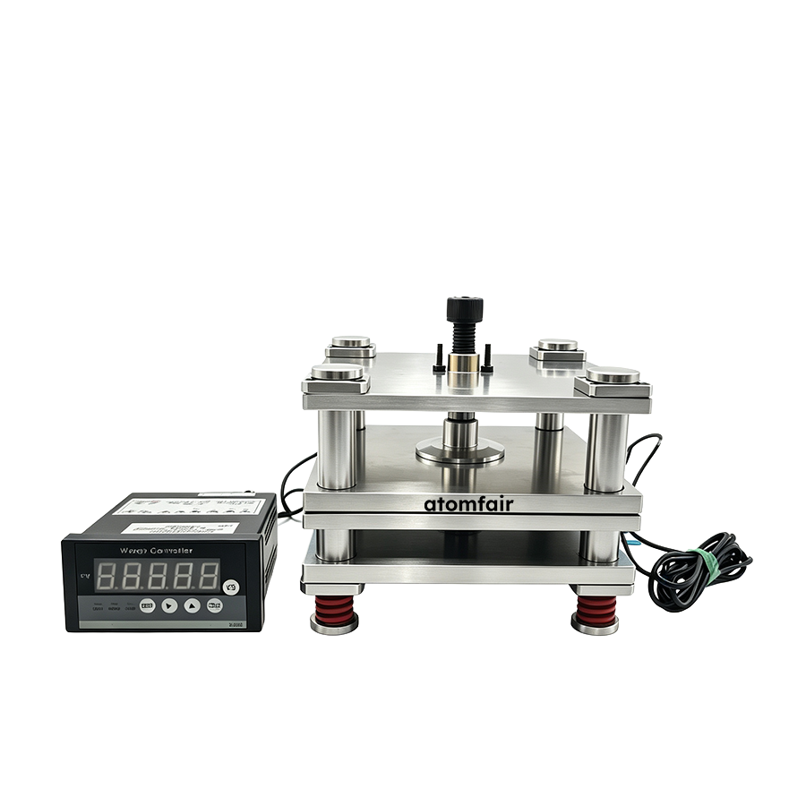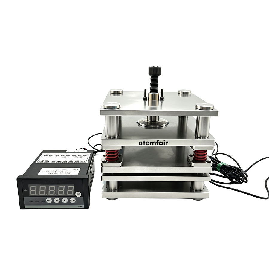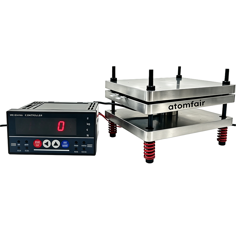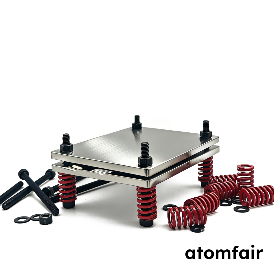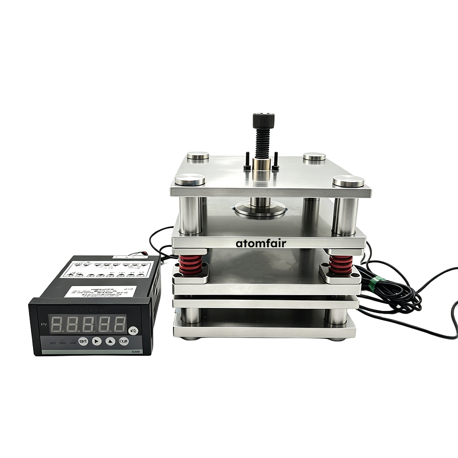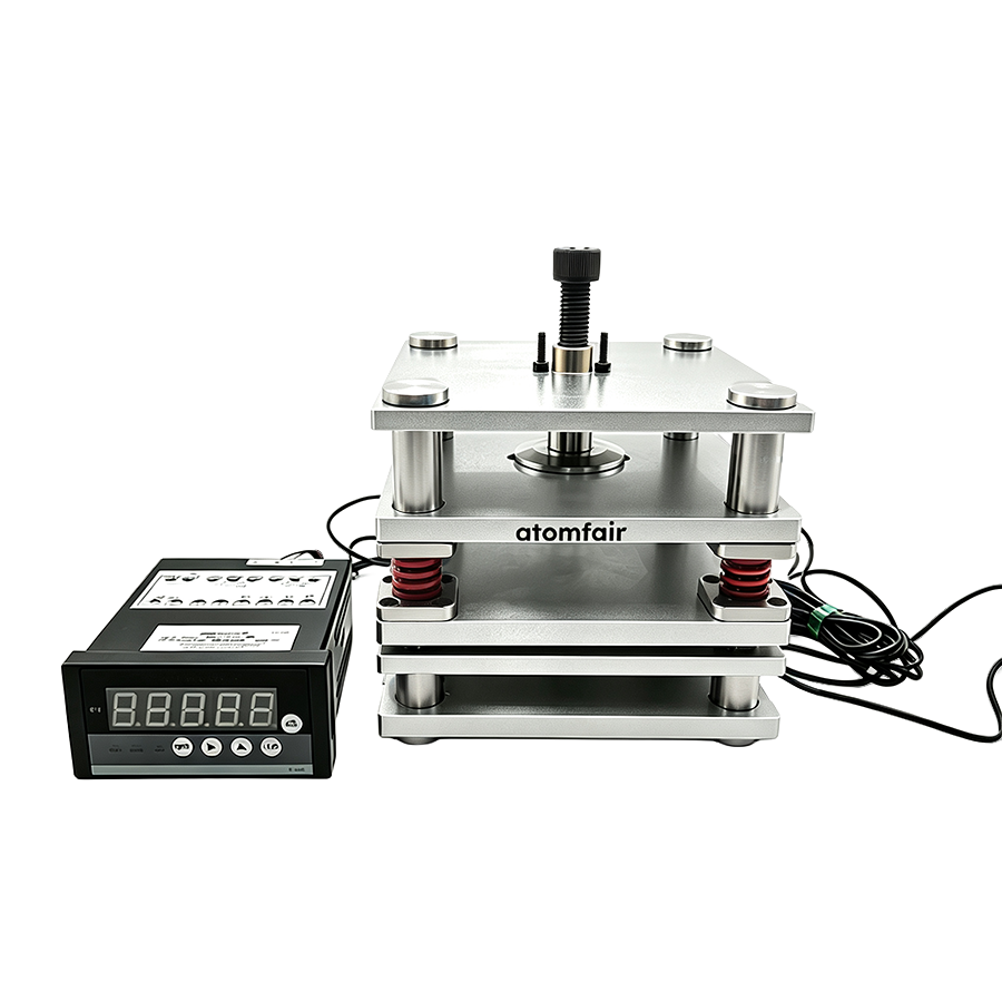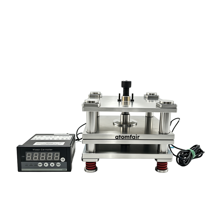
ATM-PCBT-SS316-4L 4-LAYER POUCH CELL BATTERY CYCLE TEST FIXTURERESEARCH GRADE EQUIPMENT
|
|||||||||||||||||||||||||||||||||||||||||||||||||||||||||||||||||||||||||||||||
|
|||||||||||||||||||||||||||||||||||||||||||||||||||||||||||||||||||||||||||||||
|
TAILORED SOLUTIONS FOR RESEARCH
Contact our engineering team for technical support or official institutional quotations.
EMAIL: inquiry@atomfair.com
|
|||||||||||||||||||||||||||||||||||||||||||||||||||||||||||||||||||||||||||||||
|
Manufacturer: Atomfair LLC
Brand: ATOMFAIR®
|
|||||||||||||||||||||||||||||||||||||||||||||||||||||||||||||||||||||||||||||||
This fixture requires operation within a dry room environment to prevent external signal contamination during long-term thermal validation loops. All digital connection channels must be properly insulated to avoid pressure sensor data interference.
- Environmental Requirement: Operate the fixture exclusively in a dry room environment to prevent moisture-induced signal contamination.
- Electrical Insulation: Keep all digital connection channels properly insulated to avoid pressure sensor data interference.
- Cell Protection: Use the rigid polished contact plate faces to safeguard delicate pouch cell packaging film from scratches.
- Force Uniformity: Ensure the single nut is tightened evenly to maintain uniform surface contact force across the cell casing.
- Alignment Verification: Verify parallel alignment of the four-layer stacked plates before each test cycle to ensure consistent pressure distribution.
Follow these steps to correctly install a pouch cell into the fixture and initiate cycle testing with real-time pressure monitoring. Proper alignment and environmental control are critical for reproducible data.
Required Equipment: Single nut locking mechanism, Pressure sensor cable
- Inspect Plates
Inspect all four 316 stainless steel plates for cleanliness and ensure no debris is present on the contact surfaces. - Position Cell
Place the pouch cell centrally between the plates, ensuring its dimensions do not exceed fixture length minus 30 mm. - Apply Clamping Pressure
Tighten the single nut gradually to apply the desired clamping pressure up to the standard 400 kg limit. - Connect Pressure Sensor
Connect the pressure sensor cable to the monitoring system and confirm real-time data acquisition is active. - Verify Alignment
Verify parallel alignment of the plates using a precision gauge to ensure uniform force distribution across the cell. - Control Environment
Operate the fixture within a dry room environment to prevent external signal contamination during testing. - Monitor Pressure Data
Monitor pressure sensor readings continuously throughout the cycle test to detect any drift or anomalies.
How does the plate thickness selection (10 mm vs. 12 mm) affect the maximum working pressure and structural rigidity of the ATM-PCBT-SS316-4L fixture?
The 10 mm plate versions support maximum theoretical loads of either 400 kg or 600 kg depending on dimensions, while the 12 mm reinforced versions (120×160 mm and 150×180 mm) both support 600 kg with enhanced rigidity for maintaining parallel alignment under high loads. Thicker plates ensure better force retention and uniformity during continuous testing cycles.
What is the formula for determining the maximum pouch cell size that can be tested in the ATM-PCBT-SS316-4L fixture?
The maximum cell length and width equal the fixture plate dimensions minus 30 mm. For example, a 100×130 mm fixture accommodates cells up to 70×100 mm, and a 150×180 mm fixture accommodates cells up to 120×150 mm, as explicitly stated in the dimensional calculation rule.
What operational precautions should be taken when using the pressure monitoring system on the ATM-PCBT-SS316-4L?
Keep all digital connection channels properly insulated and operate within a dry room environment to prevent external signal contamination. Monitor the fixture carefully to avoid pressure sensor data interference before initiating long-term thermal validation loops.
The ATM-PCBT-SS316-4L 4-Layer Pouch Cell Battery Cycle Test Fixture provides uniform pressure distribution via a single-nut locking mechanism and corrosion resistance from 316 stainless steel construction, but requires strict monitoring of sensor data interference and operation in dry room environments to maintain signal integrity.
Positive
- Uniform single-nut pressure distribution: The single-nut mechanical layout ensures balanced parallel load transfer across the targeted cell position, preventing stress localization during cycling.
- 316 stainless steel corrosion resistance: Full 4-layer construction of premium 316 stainless steel provides superior resistance to electrolyte acids and alkalis, maintaining flat plate parallelism in harsh environments.
Trade-offs
- Pressure sensor interference sensitivity: Digital connection channels must be properly insulated and the fixture operated in a dry room to avoid external signal contamination during long-term thermal validation loops.
- Custom sizing may be required: Standard fixture sizes limit maximum cell dimensions to 30 mm less than plate length and width; non-standard cell sizes require fully customized dimensions and spacing.
Every advanced material, component, equipment, and instrument in our catalog is backed by rigorous testing. We maintain strict internal quality management frameworks and align with CE conformity metrics to deliver transparent, reproducible performance data via our public open-science repository.
To request raw batch performance data, submit formal vendor registration paperwork, or execute a fast-turnaround R&D manufacturing loop, contact us at inquiry@atomfair.com.
Item is dispatched under the Atomfair Shipping & Delivery Framework (Free worldwide shipping on orders over $59 USD excl. heavy equipment). Return is governed by the Atomfair Return & Refund Policy (7-day technical return window).