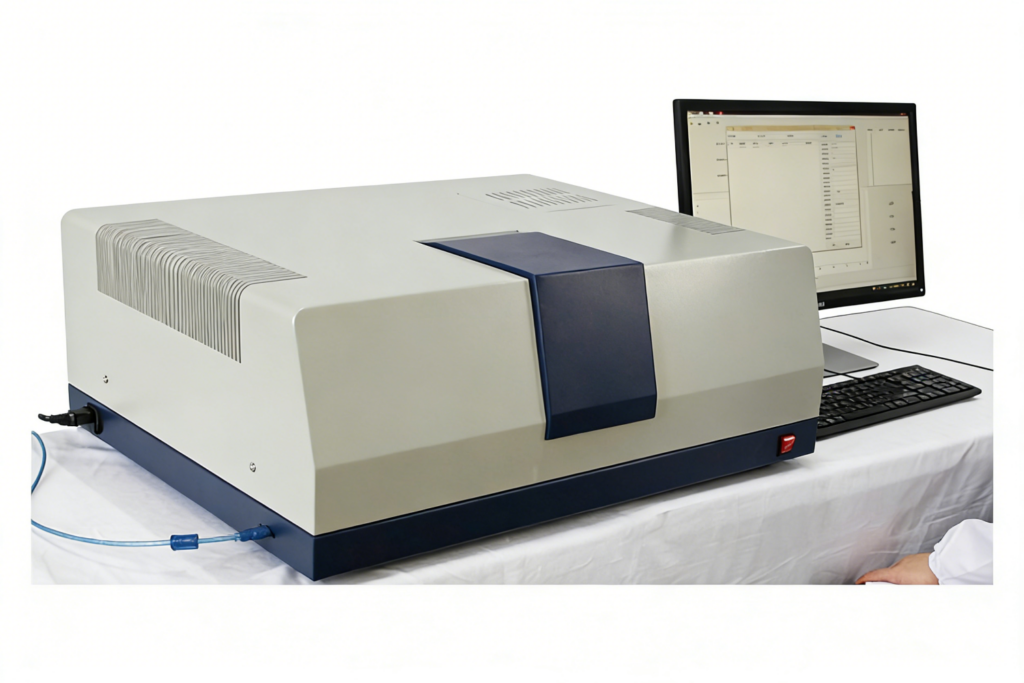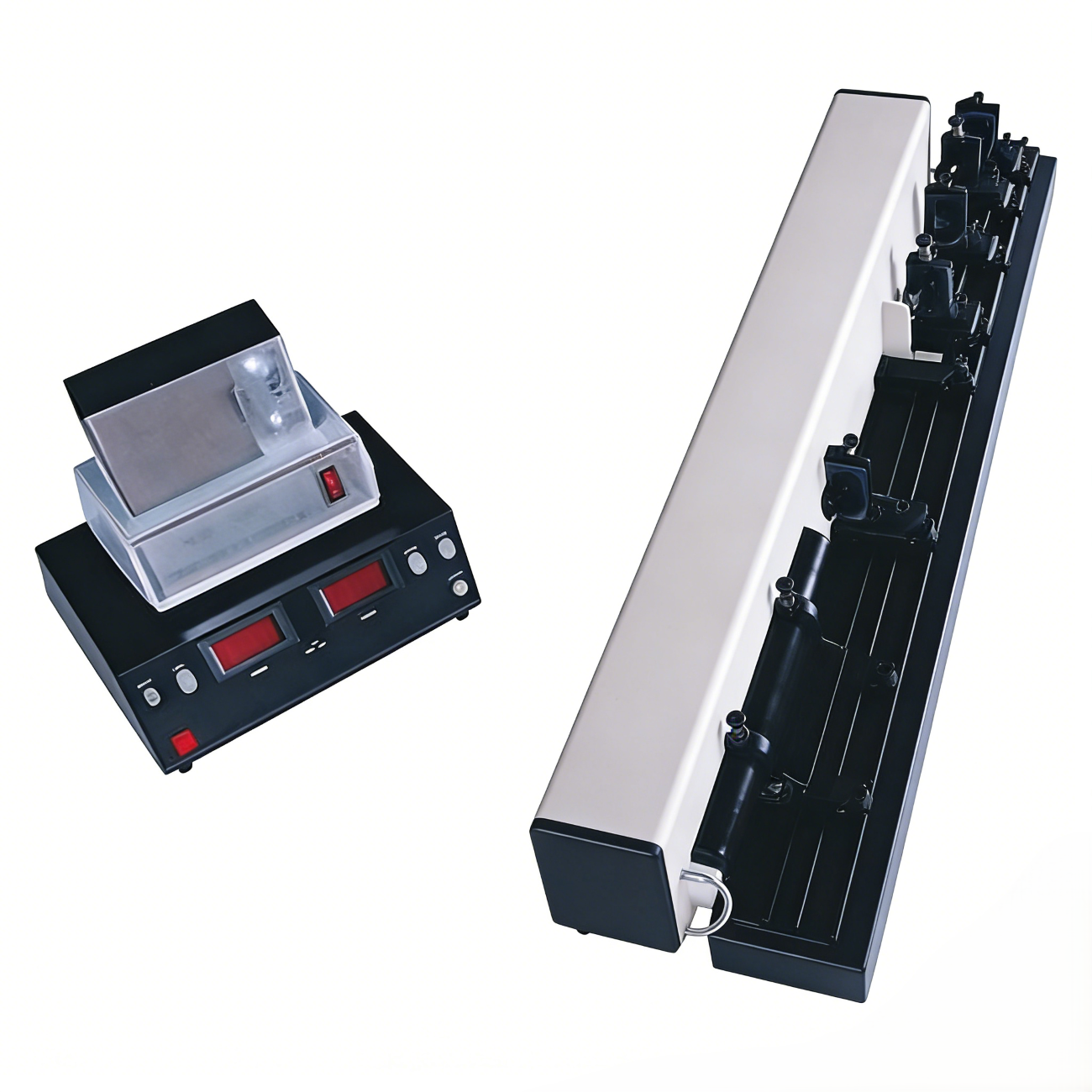
Atomfair EOM-739 Crystal Electro-Optic Modulation Tester
Product Overview
The Atomfair EOM-739 Crystal Electro-Optic Modulation Tester belongs to the optoelectronics and laser category. Based on the principle of the transverse electro-optic effect of crystals, this product leverages the phenomenon where an electric field induces a change in the refractive index of a crystal—known as the electro-optic effect. By adopting the typical LiNbO₃ crystal, it enables users to master the principles and experimental methods of crystal electro-optic modulation. With a simple experimental setup, users can measure the half-wave voltage and electro-optic constant of the crystal, observe the changes in the crystal’s optical properties caused by the electro-optic effect as well as the interference phenomenon of convergent polarized light, and conduct laser communication demonstration experiments.
Key Features
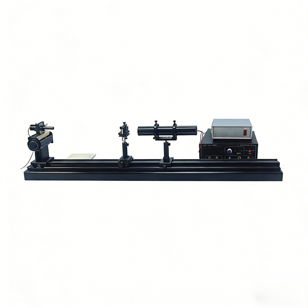
- Equipped with an aluminum alloy guide rail, the sliding seat and adjustment frame allow for precise optical path adjustment, ensuring the accuracy of experimental operations.
- Compatible with a digital dual-trace oscilloscope (optional), it can intuitively display and measure electro-optic modulation waveforms, facilitating experimental observation and data acquisition.
- The photoelectric receiver boasts high sensitivity and stable output waveforms, guaranteeing the reliability and accuracy of experimental results.
Experimental Contents
- Display electro-optic modulation waveforms and intuitively observe electro-optic modulation phenomena.
- Measure the half-wave voltage of the electro-optic crystal and further calculate the electro-optic constant.
- Conduct electro-optic modulation optical communication demonstration experiments to gain an in-depth understanding of relevant application scenarios.
Basic Configuration and Specifications
| Item No. | Name | Specifications |
|---|---|---|
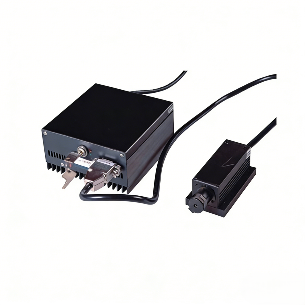
| 1 | Helium-Neon Laser | Central wavelength: 632.8nm; Output power: 1.5mW |
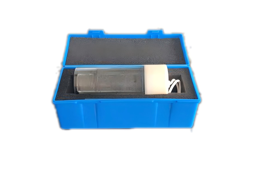
| 2 | LiNbO₃ Crystal | Electrodes: X-plane silver-plated electrodes; Flatness: <λ/8@632.8nm; Transmittance range: 420~5200nm |
| 3 | Polarizer | Light-transmitting aperture: 16mm; Wavelength range: 400-700nm; Polarization degree: 99.98%; Transmittance: 30% (parallel), 0.0045% (vertical) |
| 4 | Optical Components | Glan prism (8mm), λ/4 wave plate (10mm), ground glass plate |
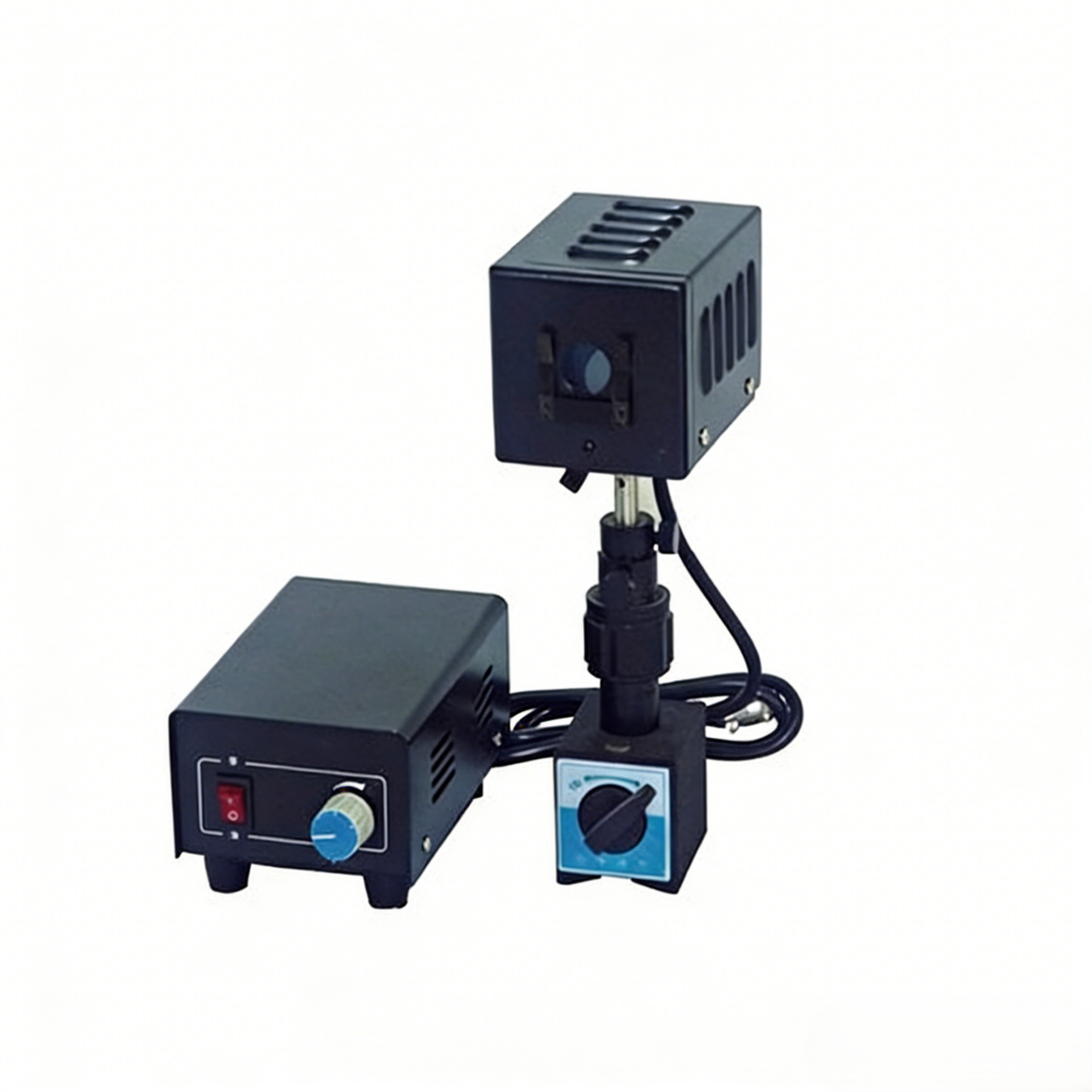
| 5 | Electro-Optic Modulation Cabinet | Output sine wave modulation amplitude: 0-300V continuously adjustable; Output DC bias voltage: 0-600V continuously adjustable; Output frequency: 1kHz |
| 6 | Photoelectric Receiver | PIN photocell |
| 7 | Rotating Frame | Minimum scale: 1° |
| 8 | Optical Guide Rail | Length: 1m; Material: Hard aluminum profile |
| 9 | Other Accessories | 4-axis adjustment frame, beam collimation hole, active speaker |
Note: The configuration and parameters listed above are for reference only. Please refer to the packing list for the actual specifications, as minor changes will not be notified separately.
If you’re interested, have any questions, or have specific customization requirements, please feel free to contact us at inquiry@atomfair.com.
The EOM-739 system contains a 1.5 mW helium-neon laser and a high-voltage modulation cabinet delivering up to 600 V DC. Precise optical alignment along the guide rail is critical for accurate electro-optic modulation measurements; misalignment degrades signal fidelity.
- Laser Exposure Hazard: Avoid direct exposure to the 632.8 nm laser beam; use appropriate eyewear if the beam path is not fully enclosed.
- Electrical Shock Risk: The modulation cabinet supplies up to 600 V DC and 300 V AC; ensure all connections are insulated before powering on.
- Optical Alignment Sensitivity: Misalignment of the polarizer, crystal, or detector reduces measurement accuracy; use the rotating frame and adjustment frames for fine tuning.
This procedure guides the user through setting up the optical path, applying modulation voltages, and measuring the half-wave voltage of the LiNbO3 crystal. An optional oscilloscope and active speaker allow waveform observation and communication demonstrations.
Required Equipment: Digital oscilloscope, Active speaker
- Mount the optical components
Mount the helium-neon laser, polarizer, LiNbO3 crystal, and photodetector sequentially along the aluminum guide rail using the provided adjustment frames. - Align the optical path
Align the optical components by adjusting the rotating frame and translation stages until the photodetector output is maximized. - Connect the modulation cabinet
Connect the electro-optic modulation cabinet output to the crystal electrodes and set the DC bias voltage to zero. - Measure the half-wave voltage
Slowly increase the DC bias voltage while monitoring the photodetector signal to identify the half-wave voltage at the first transmission minimum. - Observe the modulation waveform
Attach an oscilloscope to the photodetector output to visualize the modulation waveform, then adjust the modulation amplitude to observe waveform changes.
What is the half-wave voltage measurement range of the Atomfair EOM-739 Crystal Electro-Optic Modulation Tester?
The EOM-739 does not specify a fixed half-wave voltage range; instead, it provides a continuously adjustable DC bias voltage from 0 to 600V and a sine wave modulation amplitude from 0 to 300V at 1kHz. This allows you to measure the half-wave voltage of the LiNbO₃ crystal by sweeping the DC bias and observing the modulation waveform on an oscilloscope, as the half-wave voltage is determined by the crystal's electro-optic properties and the applied field.
Can the Atomfair EOM-739 be used with a standard oscilloscope for waveform observation?
Yes, the EOM-739 is compatible with a digital dual-trace oscilloscope (optional) to display and measure electro-optic modulation waveforms. The photoelectric receiver uses a PIN photocell with high sensitivity and stable output, ensuring reliable waveform capture. This setup is essential for observing modulation phenomena and performing quantitative measurements like half-wave voltage.
What are the optical and electrical specifications of the LiNbO₃ crystal in the EOM-739?
The LiNbO₃ crystal in the EOM-739 features X-plane silver-plated electrodes, a flatness of <λ/8 at 632.8nm, and a transmittance range of 420–5200nm. It is paired with a Helium-Neon laser at 632.8nm (1.5mW output) and a polarizer with 99.98% polarization degree. These specs ensure precise electro-optic modulation and accurate measurement of the electro-optic constant.
The Atomfair EOM-739 Crystal Electro-Optic Modulation Tester is a complete benchtop system for demonstrating the transverse electro-optic effect in LiNbO₃, enabling half-wave voltage measurement, electro-optic constant calculation, and optical communication experiments. Its integrated 1.5mW HeNe laser, 0-300V modulation and 0-600V DC bias supply, and high-sensitivity PIN receiver provide a self-contained platform for advanced photonics education and research.
Positive
- Complete electro-optic measurement platform: Integrates a 632.8nm HeNe laser, LiNbO₃ crystal, polarizer, and photoelectric receiver, enabling direct measurement of half-wave voltage and electro-optic constant without additional optical components.
- Precise optical alignment and adjustment: The 1m hard aluminum guide rail with sliding seats and 4-axis adjustment frames ensures accurate optical path alignment, critical for reliable modulation depth and waveform measurements.
Trade-offs
- Requires external oscilloscope for waveform analysis: The system outputs modulation signals but does not include a display; a digital dual-trace oscilloscope (optional) is necessary to visualize and measure the electro-optic modulation waveforms.
- High-voltage operation demands safety protocols: The DC bias supply operates up to 600V, requiring proper electrical safety training and handling procedures to prevent shock hazards during experimental setup and operation.
Every advanced material, component, equipment, and instrument in our catalog is backed by rigorous testing. We maintain strict internal quality management frameworks and align with CE conformity metrics to deliver transparent, reproducible performance data via our public open-science repository.
To request raw batch performance data, submit formal vendor registration paperwork, or execute a fast-turnaround R&D manufacturing loop, contact us at inquiry@atomfair.com.
Item is dispatched under the Atomfair Shipping & Delivery Framework (Free worldwide shipping on orders over $59 USD excl. heavy equipment). Return is governed by the Atomfair Return & Refund Policy (7-day technical return window).