Description
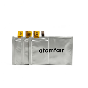
ATOMFAIR 14.5 Ah Ni90 Si/C 1350 Anode Dry Pouch CellRESEARCH GRADE CELL ARCHITECTURE
|
|||||||||||||||||||||||||||||||||||||||||||||||||||||||
|
|||||||||||||||||||||||||||||||||||||||||||||||||||||||
The dry pouch cell must be stored and handled in an inert atmosphere (argon or nitrogen) with moisture and oxygen levels below 0.1 ppm to prevent degradation of the reactive electrode materials. The cell should be maintained at 20–25°C and protected from physical puncture and electrostatic discharge during all handling steps.
- Moisture Sensitivity: Store the cell exclusively in a glovebox or dry room with dew point below -60°C.
- Oxygen Sensitivity: Never expose the unsealed cell to ambient air as oxygen triggers cathode surface reactivity and capacity loss.
- Mechanical Integrity: Inspect the pouch for pinholes or seal defects before any electrolyte filling procedure.
- Electrostatic Discharge: Use grounded wrist straps and conductive mats when handling the cell outside the glovebox.
- Temperature Stability: Keep the cell at 20–25°C to avoid thermal stress on the pouch seal and electrode coatings.
This procedure outlines the safe activation and formation cycling of the 14.5 Ah Ni90 Si/C dry pouch cell under inert atmosphere. All steps require strict adherence to glovebox protocols to ensure material integrity and accurate benchmarking.
Required Equipment: Argon-filled glovebox, Electrolyte dispensing system, Impulse heat sealer, Battery cycler
- Transfer to Glovebox
Transfer the dry pouch cell into an argon-filled glovebox with moisture and oxygen levels below 0.1 ppm. - Inspect Pouch
Inspect the pouch exterior for any pinholes, seal defects, or mechanical damage before proceeding. - Inject Electrolyte
Inject the pre-selected electrolyte formulation into the cell through the designated filling port using a precision dispenser. - Seal Filling Port
Seal the filling port immediately using an impulse heat sealer set to the pouch material's specified temperature and dwell time. - Rest for Wetting
Allow the cell to rest undisturbed for at least 24 hours to ensure complete electrolyte wetting of the electrode stack. - Perform Formation Cycling
Connect the cell to a battery cycler and perform three formation cycles at a C/20 rate within the 2.3 to 4.2 V voltage window. - Verify Capacity
Verify that the activated cell achieves a discharge capacity of at least 14.5 Ah at the formation C-rate.
What cycling stability trade-off is introduced by pairing a 1350 mAh/g Si/C anode with a Ni90 cathode in this dry pouch cell?
The 1.200 negative-to-positive (NP) capacity ratio is deliberately set to manage silicon-induced swelling, but the high anode capacity amplifies volumetric expansion and gas evolution risks during cycling. The anode compaction density of 1.0 g/cc is lower than the cathode's 3.4 g/cc, providing structural tolerance at the cost of reduced volumetric energy density. This trade-off enables systematic swelling modeling and electrolyte screening at the expense of absolute cell-level cycle life without optimized electrolyte.
Which electrolyte systems are compatible with this dry pouch cell for silicon anode research?
This dry pouch cell is explicitly designed for silicon-compatible electrolyte formulation screening; it is shipped without liquid electrolyte, allowing researchers to inject their own candidate electrolytes. The cell architecture—including the 12 μm PE separator with 2 μm Al₂O₃ ceramic coating and 1.200 NP ratio—supports a wide range of carbonate- and ether-based electrolytes but requires formulations that mitigate Si swelling and gas evolution. The cathode's ultra-high nickel content (Ni₀.₉Mn₀.₀₃Co₀.₀₇) also necessitates avoidance of acidic or moisture-contaminated electrolytes to prevent transition metal dissolution.
What handling and storage conditions are required for this Ni90 Si/C dry pouch cell before electrolyte filling?
The cell must be stored and handled in an inert atmosphere (argon glovebox or dry room) to prevent moisture adsorption onto the un-functionalized electrodes, particularly the moisture-sensitive Ni90 cathode and Si/C anode. After electrolyte filling, the cell requires rigid containment fixtures with controlled pressure (e.g., 0.5–1 MPa) to accommodate the swelling from the 1350 mAh/g Si/C anode and to maintain electrode stack alignment during gas evolution. Do not cycle the cell without a proper formation protocol under these constraints to avoid catastrophic delamination.
This dry pouch cell pairs an ultra-high nickel Ni90 cathode with a 1350 mAh/g Si/C composite anode, assembled as a 15/16 multilayer stack without electrolyte, designed for benchmarking electrolyte formulations and studying silicon swelling behavior.
Positive
- High-fidelity benchmarking platform: The dry cell architecture with precisely controlled NP ratio of 1.200 enables systematic variable elimination during electrolyte formulation screening and volumetric swelling modeling.
- Ultra-high capacity Si/C anode: The 1350 mAh/g amorphous Si/C composite anode paired with a 203 mAh/g Ni90 cathode provides an absolute capacity baseline for validating next-generation silicon-compatible electrolytes.
Trade-offs
- Requires electrolyte infusion: The cell is shipped dry without liquid electrolyte, necessitating user-controlled filling and activation steps, adding processing complexity and infrastructure demands.
- Anode swelling management needed: The ultra-high capacity Si/C anode exhibits significant volumetric expansion during cycling, requiring careful fixture pressure control and electrolyte compatibility to maintain structural integrity.
Every advanced material, component, equipment, and instrument in our catalog is backed by rigorous testing. We maintain strict internal quality management frameworks and align with CE conformity metrics to deliver transparent, reproducible performance data via our public open-science repository.
To request raw batch performance data, submit formal vendor registration paperwork, or execute a fast-turnaround R&D manufacturing loop, contact us at inquiry@atomfair.com.
Item is dispatched under the Atomfair Shipping & Delivery Framework (Free worldwide shipping on orders over $59 USD). Return is governed by the Atomfair Return & Refund Policy (7-day technical return window).