Lab Accessories & Consumables
Lab Accessories & Consumables
In battery R&D, non-active components and precision tools directly dictate cell mechanical stability, packaging integrity, and electrochemical reproducibility. Minor processing variances—such as tab sealing, crimper pressure, or mold stress distribution—can induce performance drift, high impedance, or shortened lifecycle.
ATOMFAIR supplies a traceable, high-purity laboratory matrix including: customizable coin/pouch/cylindrical cases and tabs; manual/electric sealing and slitting equipment; low-resistance fixtures, probes, and split cells; alongside essential measurement and doctor-blade coating tools. Standardized on rigorous batch consistency, our portfolio seamlessly supports initial prototype line setup and solid-state interface contact optimization.
SHOW CONSUMABLE MATRIX & TECHNICAL SPECIFICATIONS
I. Battery Cases & Packaging Consumables
We provide complete sets of materials from cases to packaging for coin, pouch, cylindrical, and solid-state batteries, effectively solving leakage and short-circuit issues caused by mismatched case dimensions, incompatible sealing materials, or uncontrollable internal pressure, while supporting non-standard system customization and three-electrode configuration designs.
1.1 Battery Cases
| Product Name | Material / Specifications | Purpose / Description |
|---|---|---|
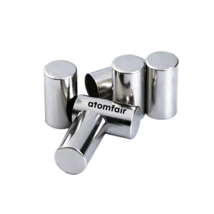
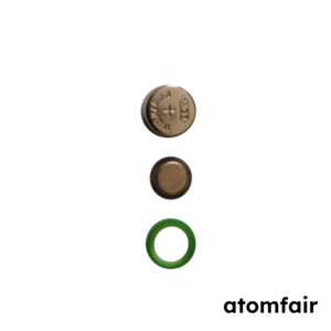
| Coin Cell Cases (with Internal Accessories) | Case: Stainless steel 304, 316L, gold-plated, titanium-plated, nickel-plated, aluminum-plated; standard models CR2032/CR2025/CR2016, etc.; customizable dimensions and openings. Internal Accessories: Coin cell wave springs (wave/multi-fold wave/conical springs, etc.) multiple specifications; stainless steel spacers Φ15–20mm, thickness 0.5–2.0mm; insulating gaskets PP/PTFE, internal diameter 16–19mm. |
Coin cell packaging, positive and negative cases come with built-in insulation gaskets. Internal accessories are used to adjust stacking thickness, maintain pressure consistency, and achieve electrical insulation between positive and negative electrodes. |
| Cylindrical Cell Cases | 18650 / 21700 / 26650, nickel-plated steel or stainless steel 304, caps included | Cylindrical cell assembly. |
| Prismatic Aluminum Cases | Aluminum 6061 or 304 stainless steel, customizable dimensions | Prismatic aluminum/steel cell cases shell. |
1.2 Packaging Materials
| Product Name | Material / Specifications | Purpose / Description |
|---|---|---|
| Aluminum Laminated Film (Alu-plastic Film) | Nylon/Aluminum foil/PP three-layer composite, thickness 88–152μm | Outer packaging for pouch cells, featuring high heat-sealing strength and excellent water/oxygen barriers. |
| Battery Tabs | Aluminum / Nickel / Nickel-plated copper, width 2–20mm, customizable sealant tape position | Positive and negative terminal extensions, perfectly compatible with heat-sealable tab sealant tape. |
| Tab Sealant Tape (Tab Film) | White sealant / Black sealant, electrolyte resistant, customizable width | Sealing and heat-sealing layer for pouch cell battery tabs. |
1.3 Insulating Materials
| Product Name | Material / Specifications | Purpose / Description |
|---|---|---|
| Insulating Gaskets | PP / PE / Polyimide (PI), thickness 0.1–0.5mm | Prevents internal short-circuiting inside pouch/prismatic cell configurations. |
| Insulating Tapes | Amber Polyimide (PI) tape / Green PET tape | Insulation wrapping for tab extensions and electrode sheet edges. |
II.Battery Fixtures, Molds & Testing Accessories
We provide low contact resistance fixtures, four-wire test cables, high-pressure-resistant molds, and multi-configuration cells for charge-discharge testing, solid-state battery formation, and three-electrode analysis, helping users minimize system measurement errors and enhance the authenticity and comparability of impedance spectra and cycling data.
| Product Name | Material / Specifications | Purpose / Description |
|---|---|---|
| Battery Fixtures / Testing Racks | Stainless steel / PTFE / PEEK / Carbon steel / Alloy; 2-layer, 3-layer, or 4-layer configurations | Securing batteries for charge-discharge testing, offering low contact resistance. |
| Battery Bases / Holders | Stainless steel / Polytetrafluoroethylene (PTFE) | Used in combination with sealing machines or testing racks to provide robust structural support. |
| Solid-State Battery Molds | Φ10–20mm, single-axial / bi-axial compression, PEEK insulation housing | Pressing and molding of solid electrolytes, compression tolerance ≥300MPa. |
| Two-Electrode Split Test Cells | Coin / Pouch / Swagelok types | Conventional charge-discharge evaluation, two-electrode system validation. |
| Three-Electrode Split Test Cells | Coin / Pouch / Swagelok types, reference electrode terminal included | Lithium plating analysis, impedance decomposition, and in-situ electrode potential monitoring. |
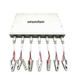
| Testing Probes / Pins | Gold-plated / Nickel-plated, pogo pins or alligator clips | Connecting cell tabs or cases to measurement test cables. |
| Battery Test Leads / Cables | Four-wire shielded cables, BNC / Alligator clips / Banana plugs available | Minimizes cable resistance and signal interference, fully adapted to mainstream testing cabinets. |
| Solid Electrolyte Pellet Pressing Molds | Diameter 10–15mm, premium stainless steel | Works with laboratory pellet press machines to compress solid electrolyte discs. |
| “>High-Temperature Test Fixtures | Room temperature to 150°C, integrated with Type K thermocouple | Dedicated to solid-state batteries or elevated-temperature electrochemical testing. |
III.Measurement Instruments, Manual Tools & Compact Auxiliary Equipment
We provide a full suite of instruments and tools for electrode thickness measurement, microfluidic liquid transfer, slurry dispersion, ultrasonic cleaning, and in-situ expansion monitoring, meeting laboratory requirements for precision, operational safety, and data traceability while simplifying equipment selection and maintenance.
| Product Name | Specifications / Parameters | Purpose / Description |
|---|---|---|
| Micrometer | Digital / Dial display, 0–25mm range, 0.001mm precision | Measuring the thickness of electrode sheets, separators, and cell cases. |
| High-Precision Analytical Balance | Precision 0.1mg / 0.01mg, capacity 120g/220g | Weighing active substances, conductive agents, and binders. |
| Vernier Caliper | Digital display, 150mm/200mm range, 0.01mm accuracy | Measuring external battery dimensions and electrode sheet sizing. |
| Moisture Analyzer | Karl Fischer coulometric titration method, 1ppm resolution | Detecting trace moisture content in electrolytes, powders, and separators. |
| Film Thickness Gauge | Adjustable measuring force 0.1–0.5N, 0.1μm resolution | Thickness measurement for soft separators and electrode coatings. |
| Micro Pipette | 10–100μL / 100–1000μL adjustable volume ranges | Precise electrolyte injection and microfluidic liquid transfer. |
| Compact Ultrasonic Cleaner | Ultrasonic power 50W, capacity 1–3L | Cleaning component molds, cell cases, and testing fixtures. |
| Magnetic Stirrer | Rotation speed 100–1500rpm, magnetic bars included | Slurry homogenization and component powder dispersion. |
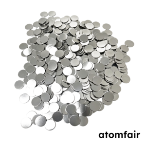
| Electrode Sheet Puncher | Punch diameter Φ8–20mm, premium stainless steel | Harvesting small-diameter electrode discs directly from coated electrode sheets. |
| Doctor Blade / Film Coater | Adjustable micrometer gap 5–500μm, stainless steel | Manual doctor-blade coating of customized electrode slurry. |
| Displacement Sensor | Resolution 0.1μm, measurement range 0–10mm | In-situ monitoring of electrode thickness expansion and overall battery volume changes. |
Technical FAQ for Cell Assembly Process, Solid-State Molds & Electrochemical Testing
1. During coin cell assembly, using the same case depth, wave spring, and spacer combinations, why does the internal resistance (DCR) between different batches still show significant dispersion?
Internal resistance dispersion typically does not originate from the wave spring itself, but rather from the actual thickness variations of the electrode stack after layering (driven by fluctuations in positive/negative coating areal density and compacted density) coupled with the non-linear compression curve of the spring. When the total stacking thickness deviates from the linear zone of the wave spring compression profile (e.g., if the compression of the wave spring is under 0.2mm or exceeds 0.8mm), the applied stress changes drastically, which directly impairs solid-phase contact resistance. It is highly recommended to use a vernier caliper to physically measure the total stacked height of each cell to back-calculate spring compression, ensuring it falls within the middle section of the spring’s linear range (typically 30% to 60% of its free height).
2. After deep-drawing an aluminum laminated film, how can microcracks within the aluminum foil layer be detected without damaging the sample?
Conventional visual inspection cannot detect structural microcracks. A standard laboratory approach is the electrolyte penetration method: inject a fluorine-containing electrolyte into the deep-drawn pit of the aluminum laminated film, let it stand at 60°C for 24 hours, and then use a fluorine ion-selective electrode to test the fluorine ion concentration on the outer surface of the pit. Alternatively, a high-voltage electric spark pinhole detector can be deployed (using the internal aluminum foil as an electrode to catch sudden current spikes), which can accurately locate micro-pores ≥5μm. The latter is a non-destructive testing method, highly suitable for small-batch validation.
3. After heat-sealing the battery tab sealant tape and the aluminum laminated film, continuous “tunnel-like” bubbles occasionally appear at the interface. What causes this?
This phenomenon is known as “channel pinning or tunneling pores.” The fundamental cause is a mismatch between the Melt Flow Index (MFI) of the tab sealant tape and the inner PP layer of the aluminum laminated film, causing the two melts to flow at significantly different velocities under heat-sealing pressure, which entrap ambient air along the interface. If the tab film flows too quickly, it wraps and traps air pockets; if it flows too slowly, it fails to adequately fill the microscopic roughness of the aluminum laminated film surface. Resolving this requires matching their MFI values (a difference of ≤5g/10min under 230°C/2.16kg is recommended) and optimizing the heat-sealing temperature gradient.
4. In a three-electrode coin cell, is a long-term drift of the reference potential (>10mV/24h) normal? How do you distinguish whether the reference electrode has failed or the electrolyte has decomposed?
A lithium wire reference electrode in conventional carbonate-based electrolytes typically exhibits a potential drift of <5mV/24h. If the drift exceeds 10mV, first verify whether the reference electrode has made direct contact with the working or counter electrode sheets (causing localized micro-short circuits). If no short circuit exists, apply a small current pulse (±10μA, 10s) to the cell and observe whether an ohmic spike appears on the reference potential profile. If the potential returns to its baseline value after the spike, the reference interface remains stable; if it shifts continuously, it indicates that impurities in the electrolyte (such as trace H2O or HF) are forming a high-impedance passivation layer on the lithium wire surface. Replacing it with fresh electrolyte can replicate and verify the baseline.
5. Within solid-state battery molds, what is the difference in impact between bi-axial and single-axial compression on the compactness of solid electrolyte pellets?
During single-axial compression, pressure is delivered from only one end. Particle-to-wall friction generates a vertical pressure gradient, resulting in a higher pellet density near the moving punch and lower density at the far end, alongside an uneven distribution of internal shear stress that triggers delamination or edge cracking post-molding. In contrast, bi-axial compression (where top and bottom punches move toward each other simultaneously) drastically minimizes the internal pressure gradient, yielding a significantly more uniform axial density distribution (the density variance can drop from 10% under single-axial to within 3% under bi-axial), making it particularly essential for electrolyte pellets with a thickness >2mm.
6. When a dry electrode sheet slitter cuts composite electrode sheets (such as NCM cathodes), why do “sawtooth-like” delaminations frequently occur along the coating edges?
This occurs because the peeling strength between the active coating layer and the current collector foil is insufficient to withstand the combined tensile-shear stress during slitting. When the clearance gap between the upper and lower blades is too large, the electrode sheet undergoes stretching distortion before fracturing. The brittle ceramic active coating cracks under this tensile stress and propagates through its thickness, causing jagged edge delamination. Minimizing the blade clearance to 5% to 10% of the foil thickness and incorporating a spring-loaded stripper plate to firmly pre-compress the coating area before shearing will significantly eliminate edge peeling.
7. In a high-temperature test fixture (150°C), where should the measurement tip of a Type K thermocouple be secured to register the true core cell temperature?
There is a severe thermal gradient between the inner core of a cell and its outer surface, particularly in solid-state batteries due to high solid-solid interfacial thermal resistance. Securing the thermocouple directly to the outer surface of the heavy fixture can yield a readout 5°C to 15°C lower than the core reaction area. It is recommended to place a 0.2mm to 0.5mm thick flexible thermal pad (silicone-based, thermal conductivity >3W/m·K) between the fixture wall and the positive case shell of the battery, embedding the thermocouple tip inside this pad to stay flush against the positive shell. For coin cells, the positive case shell is the most accessible point matching the inner reaction zone.
8. When using a displacement sensor to monitor pouch cell thickness expansion, why does the initial thickness of a newly assembled battery slowly decrease over time?
This phenomenon is known as structural relaxation, primarily driven by two factors: ① the microscopic voids between the separator and the electrodes gradually close up under slight contact pre-load (physical creep); ② the chemical swelling of the electrode matrices after electrolyte wet-out takes several hours to days to reach equilibrium (chemical relaxation). If recording begins immediately, the sensor will misinterpret this structural relaxation as negative expansion. It is highly recommended to let the cell rest under an open-circuit state for 12 to 24 hours post-injection and sealing, and initiate in-situ cycle testing only after the thickness change rate stabilizes to <1μm/h.
Showing 1–16 of 90 results
-
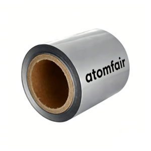
113μm Aluminum Laminated Film 200mm × 10m ATOMFAIR®
$89.00 -

18650 Nickel-Plated Steel Battery Case Kit 100pk ATOMFAIR®
$125.00 -
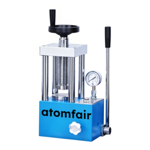
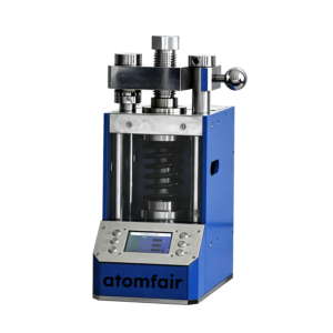
2-Column Powder Tablet Press 0-15 Ton Φ70mm ATOMFAIR®
$1,608.00 -
21700 Cylindrical Battery Case Kit Research Grade ATOMFAIR®
$152.00 -

26650 Cylindrical Battery Case 0.25mm SS304 ATOMFAIR®
$154.00 -

304/316L Stainless Conical Springs 15.4×1.1mm ATOMFAIR®
$130.00 -
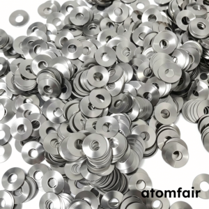
304/316L Stainless Steel Conductive Spacers 15.8×0.5mm ATOMFAIR®
$122.00 -
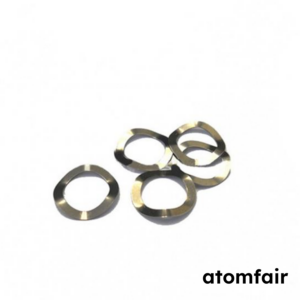
304/316L Stainless Steel Wave Springs 15.4mm ATOMFAIR®
$130.00 -
316 Stainless Steel LR41 Coin Cell Case 100-pack ATOMFAIR®
$190.00 -

4680 Tabless Cell Assembly Kit 25pk Research Grade ATOMFAIR®
$170.00 -
5V 8-Channel Coin Cell Battery Tester 10/20/50mA ATOMFAIR®
$1,799.50 -
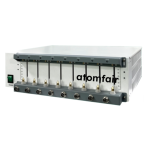
5V6A 8-Channel Battery Tester for Coin Cells ATOMFAIR®
Price range: $1,199.00 through $2,299.00 -
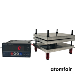
Adjustable Pressure Jig & Load Sensor 78x100mm – ATOMFAIR®
Price range: $299.95 through $529.95 -
AFP-749 Fluorescence Pellet Press (0-60 Ton) ATOMFAIR®
$7,103.00 -
Al-Clad Conical Springs 15.4mm CR2032 ATOMFAIR®
$75.00 -

Al-Clad Wave Springs 15.4mm CR2032 Research Grade ATOMFAIR®
$100.00