Description
ATOMFAIR® ATM-PCBT-AA POUCH CELL BATTERY TEST FIXTURE (ALUMINUM ALLOY VERSION)
|
|||||||||||||||||||||||||||||||||||||||||||
|
|
|||||||||||||||||||||||||||||||||||||||||||
|
TAILORED SOLUTIONS FOR RESEARCH
Contact our engineering team for technical support, personalized configuration variants, or custom institutional quotations.
EMAIL: inquiry@atomfair.com
|
|||||||||||||||||||||||||||||||||||||||||||
|
Manufacturer: Atomfair LLC
Brand: ATOMFAIR®
|
|||||||||||||||||||||||||||||||||||||||||||
The Atomfair Pouch Cell Battery Test Fixture requires careful material selection to match electrolyte exposure conditions. The clamping pressure must remain within the rated 250-350 kg range to avoid mechanical failure or cell damage.
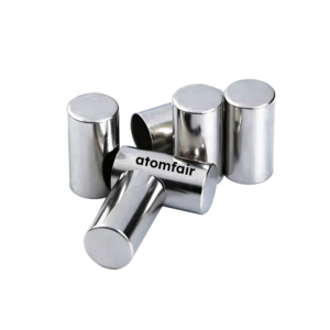
- Material Compatibility: Select stainless steel variants (304 or 316) for direct electrolyte contact, or use anodized aluminum alloys for mild exposure to ensure corrosion resistance and electrical insulation.
- Size Constraint: Ensure the pouch cell dimensions are at least 30 mm smaller in both length and width than the fixture dimensions to guarantee proper clamping and clearance.
- Pressure Limit: Do not exceed the maximum theoretical load specified for the fixture size, as over-pressurization can lead to fixture deformation or cell rupture.
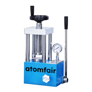
- Clamping Procedure: Apply uniform pressure by tightening the four-corner screws in a cross pattern, allowing the die spring buffer to equalize the load across the cell.
- Insulation Requirement: Use anodized aluminum or non-conductive materials for fixtures in electrical testing to prevent short circuits between the battery terminals and the fixture.
Select the appropriate fixture size based on the pouch cell dimensions. Insert the cell, then tighten the screws to the specified working pressure.
Required Equipment:
- Fixture Selection
Select a fixture size such that the cell length and width are each 30 millimeters less than the fixture dimensions. - Cell Placement
Place the pouch cell between the fixture plates, centering it on the die spring buffer for uniform pressure distribution. - Pressure Application
Tighten the four-corner locking screws evenly in a cross pattern until the die spring indicates the desired working pressure.
What are the key performance trade-offs between selecting 7075-T6 aluminum alloy and 316 stainless steel for the ATM-PCBT-AA pouch cell test fixture?
7075-T6 aluminum alloy offers the highest strength among aluminum alloys with good rigidity and is lightweight, but its electrolyte resistance is only mild compared to 316 stainless steel. 316 stainless steel provides the best electrolyte corrosion resistance, is non-magnetic, and supports high pressure up to 500 kg, but is heavier. The choice depends on whether lightweight handling for routine cycling or maximum corrosion protection in electrolyte leakage scenarios is prioritized.
How do I determine the maximum pouch cell dimensions that can be tested in the ATM-PCBT-AA fixture?
The maximum cell length and width are equal to the chosen fixture size minus 30 mm in each dimension. For example, a fixture size of 8×150×180 mm accepts cells ≤25×120×150 mm using the standard 30 mm safety margin to protect the cell edges. The fixture also accommodates battery thicknesses from 0.1 to 2 cm as a global constraint.
Does the aluminum alloy version of the pouch cell test fixture provide sufficient electrical insulation for safe battery cycling, or is additional insulation needed?
The aluminum alloy fixture can be anodized to enhance insulation and corrosion resistance, providing a scratch-proof, insulating surface suitable for most battery cycling tests. For higher-voltage or leakage-prone applications, engineering plastic options such as PEEK or PPS offer superior non-conductive and electrolyte-resistant properties without requiring anodizing.
This pouch cell test fixture uses a lightweight aluminum alloy construction with an anodized finish for insulation and corrosion resistance, offering standard 250 kg clamping pressure (upgradable to 350 kg) and accommodating cell thicknesses from 0.1 to 2 cm. The four-corner screw locking with die spring buffer provides consistent pressure, and the 30 mm safety margin rule protects the cell during cycling.
Positive
- Lightweight aluminum alloy construction: Aluminum alloy (e.g., 7075-T6) offers high strength-to-weight ratio, good rigidity, and can be anodized for insulation and scratch resistance, making handling and precise positioning easier.
- Four-corner screw locking with die spring buffer: The clamping system uses four-corner screws with a die spring buffer to apply uniform, controlled pressure, improving test reproducibility and protecting the cell from mechanical stress.
Trade-offs
- Standard working pressure limited to 250 kg: The basic version provides a standard working pressure of 250 kg, which may be insufficient for high-compression testing protocols; customization to 350 kg is available but not standard.
- Cell thickness range 0.1–2 cm only: The fixture is designed for pouch cells with thicknesses between 0.1 and 2 cm, excluding thicker cells that may require alternative fixtures or custom adaptations.
Every advanced material, component, equipment, and instrument in our catalog is backed by rigorous testing. We maintain strict internal quality management frameworks and align with CE conformity metrics to deliver transparent, reproducible performance data via our public open-science repository.
To request raw batch performance data, submit formal vendor registration paperwork, or execute a fast-turnaround R&D manufacturing loop, contact us at inquiry@atomfair.com.
Item is dispatched under the Atomfair Shipping & Delivery Framework (Free worldwide shipping on orders over $59 USD). Return is governed by the Atomfair Return & Refund Policy (7-day technical return window).