Description
ATOMFAIR® ATM-PCBT-AC POUCH CELL BATTERY TEST FIXTURE (ACRYLIC BASIC VERSION)RESEARCH GRADE MATERIAL
|
|||||||||||||||||||||||||||||||||||||||||||
|
|||||||||||||||||||||||||||||||||||||||||||
|
TAILORED SOLUTIONS FOR RESEARCH
Contact our engineering team for technical support, personalized configuration variants, or custom institutional quotations.
EMAIL: inquiry@atomfair.com
|
|||||||||||||||||||||||||||||||||||||||||||
|
Manufacturer: Atomfair LLC
Brand: ATOMFAIR®
|
|||||||||||||||||||||||||||||||||||||||||||
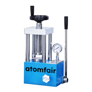
This fixture applies a configurable clamping pressure up to 180 kg to pouch cells during cycle testing. Material selection must account for electrolyte compatibility and mechanical load limits to avoid cell damage or fixture failure.
- Pressure Limit: The standard working pressure is 120 kg, customizable up to 180 kg for specific fixture variants.
- Cell Size Compatibility: Fixture size must be at least 30 mm larger than the cell dimensions in both length and width.
- Thickness Range: The compatible battery thickness ranges from 0.1 to 1.2 cm.
- Material Compatibility: Acrylic is suitable for visual observation but not recommended for electrolyte leakage scenarios; stainless steel 316 offers the best electrolyte corrosion resistance.
The fixture secures pouch cells under controlled pressure for cycle testing. Proper setup requires matching cell dimensions to fixture size and adjusting clamping force within rated limits.
Required Equipment: Pouch cell battery test fixture (ATM-PCBT-AC) with die spring buffer
- Select Fixture Size
Select a fixture size such that the cell length and width are at least 30 mm smaller than the fixture dimensions. - Position the Cell
Place the pouch cell inside the fixture ensuring proper alignment with the clamping area. - Apply Clamping Pressure
Tighten the four corner screws evenly using the die spring buffer to achieve the target clamping pressure. - Verify Pressure Distribution
Inspect the cell for uniform pressure distribution before starting the cycle test.
For the acrylic basic version of the ATM-PCBT-AC pouch cell fixture, what is the maximum working pressure and how does the 180 kg load limit affect its suitability compared to stainless steel fixtures for high-pressure cycle testing?
The acrylic basic version offers a standard working pressure of 120 kg and can be customized up to 180 kg maximum, making it suitable for medium-to-low pressure testing. In contrast, 316 stainless steel fixtures support loads from 0 to 500 kg, enabling high-pressure experiments but sacrificing the transparency that acrylic provides for real-time visual observation of cell swelling and leakage.
What are the exact dimensional constraints for fitting a pouch cell into the ATM-PCBT-AC fixture, and why is the 30 mm margin required for length and width?
The fixture sizing rule mandates that the maximum cell length and width must be exactly 30 mm less than the fixture dimensions; for example, an 8×100×130 mm fixture accommodates cells ≤8×70×100 mm. This 30 mm margin provides safe clamping space to protect both the cell and the acrylic fixture, ensuring stable battery cycle testing data and unobstructed observation.
How does the die spring buffer in the 4-corner screw locking mechanism protect both the cell and the acrylic fixture during battery cycle testing?
The die spring buffer acts as a soft buffer that prevents over-tightening and absorbs mechanical shock, safeguarding the pouch cell and acrylic fixture from damage during clamping and cycling. This design accommodates minor cell swelling without cracking the acrylic, maintaining consistent pressure for reliable test results while allowing visual inspection of the cell surface.
This acrylic pouch cell test fixture offers transparency for real-time observation of cell swelling and leakage, with customization of size, material, and pressure. However, the acrylic formulation limits maximum clamping pressure to 180 kg, and the 30 mm sizing rule reduces usable cell area relative to fixture dimensions.
Positive
- Transparent acrylic enables visual monitoring: The acrylic material provides high transparency, allowing real-time observation of cell swelling and electrolyte leakage during battery cycle testing without removing the fixture.
- Fully customizable size, material, and pressure: Fixture dimensions, material selection (acrylic, stainless steel, aluminum, plastics), and clamping pressure can be tailored to specific cell sizes and testing requirements, including up to 180 kg with acrylic and higher with other materials.
Trade-offs
- Acrylic limited to 180 kg maximum pressure: The standard acrylic fixture is designed for medium and low pressure testing only, with a maximum theoretical load of 180 kg, restricting use in high-pressure compression studies.
- Cell dimensions reduced by 30 mm per side: To ensure safe clamping clearance and protect the cell and acrylic, the maximum compatible cell length and width must be 30 mm smaller than the fixture dimensions, reducing effective working area.
Every advanced material, component, equipment, and instrument in our catalog is backed by rigorous testing. We maintain strict internal quality management frameworks and align with CE conformity metrics to deliver transparent, reproducible performance data via our public open-science repository.
To request raw batch performance data, submit formal vendor registration paperwork, or execute a fast-turnaround R&D manufacturing loop, contact us at inquiry@atomfair.com.
Item is dispatched under the Atomfair Shipping & Delivery Framework (Free worldwide shipping on orders over $59 USD). Return is governed by the Atomfair Return & Refund Policy (7-day technical return window).