Description
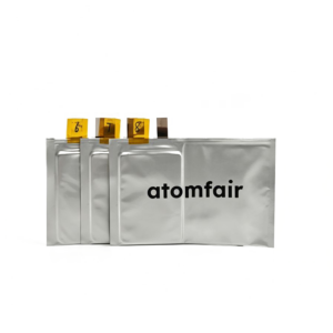
310 Wh/kg High Energy Density Lithium-Ion Pouch Cell | ATOMFAIRCOMMERCIAL GRADE · PRODUCTION
|
|||||||||||||||||||||||||||||||||||||||||||||||||||
|
|||||||||||||||||||||||||||||||||||||||||||||||||||
|
TAILORED SOLUTIONS FOR RESEARCH
Contact our engineering team for technical support or official institutional quotations.
EMAIL: INQUIRY@ATOMFAIR.COM
|
|||||||||||||||||||||||||||||||||||||||||||||||||||
|
MANUFACTURER: ATOMFAIR LLC
BRAND: ATOMFAIR®
|
|||||||||||||||||||||||||||||||||||||||||||||||||||
This pouch cell requires strict environmental and electrical management to prevent thermal runaway and mechanical failure. Storage must be within 15 °C to 30 °C in a dry, ventilated enclosure with original packaging until use.
- Thermal Storage Range: Store the cell between 15 °C and 30 °C in a dry, ventilated space to prevent degradation and swelling.
- Original Packaging Requirement: Keep the cell inside its original environmental isolation wrapper until final system integration to avoid moisture ingress.
- Prohibited Actions: Never disassemble the pouch structure or expose terminals to open flame to prevent fire or electrolyte release.
- Electrical Management Mandate: Connect the cell exclusively to a multi-channel battery management system with overcurrent and sub-zero charge cutoff protection.
- Mechanical Stress Warning: Avoid mechanical stress and internal volume expansion by securing the cell with appropriate compression fixtures.
Follow these steps to safely handle, store, and initialize the high-energy pouch cell for integration. Proper procedure minimizes risk of damage or thermal events.
Required Equipment: Multi-channel battery management system (BMS) with overcurrent cutoff, Dry, ventilated storage cabinet (15 °C–30 °C), Insulated gloves and non-conductive work surface
- Inspect Cell
Inspect the pouch cell for any visible dents, punctures, or swelling before removing the packaging. - Store Properly
Transfer the cell to a dry, ventilated storage cabinet maintained at 15 °C to 30 °C if not immediately used. - Connect BMS
Connect the cell terminals to a multi-channel battery management system configured with overcurrent and sub-zero charge protection. - Charge Safely
Set the charge current to 0.5 C and verify ambient temperature is between 0 °C and 45 °C before initiating charging. - Mechanical Fixation
Apply a controlled mechanical constraint to the cell stack to accommodate volume expansion during cycling.
What performance trade-off exists between the 310 Wh/kg energy density and the cycle life for this NMC/Gr+SiOx pouch cell?
The cell achieves 310 Wh/kg with a cycle life of ≥500 cycles at 0.5C/0.5C under 25°C, representing a practical balance for high-energy applications. While higher energy density often reduces cycle life, this cell retains coulombic efficiency >99.5% under standard conditions. Discharge at the maximum 3.0C continuous or 5.0C pulse (30s) may shorten cycle life relative to the rated 0.5C standard.
What BMS or protection circuit specifications are required for integrating this high-energy pouch cell into a battery pack?
The operational compliance notice mandates use of multi-channel management cards with integrated overcurrent and sub-zero charge cutoff relays. The charge temperature range is 0°C to 45°C and discharge range is -20°C to 60°C, with a voltage window of 4.25V to 2.50V. Given the cell's vulnerability to volume expansion and overcharge potentials, the BMS must also provide individual cell balancing and strict voltage monitoring.
What are the recommended storage and handling precautions for this 310 Wh/kg pouch cell to ensure operational safety?
Store cells in their original environmental isolation wrappers in a dry, ventilated space held between 15°C and 30°C. Never disassemble the pouch or expose terminals to open flame. During system integration, use a BMS with overcurrent and sub-zero charge cutoff, and physically protect the cell from mechanical stress due to its susceptibility to internal volume expansion.
This 310 Wh/kg NMC/Gr+SiOx pouch cell delivers industry-leading gravimetric energy density with ≥500 cycle life and 3.0C continuous discharge, but requires careful handling due to sensitivity to mechanical stress and strict storage conditions.
Positive
- High gravimetric and volumetric density: Achieves ≥310 Wh/kg and ≥700 Wh/L at 0.2C using NMC/Gr+SiOx chemistry, enabling compact high-capacity energy storage for demanding applications.
- Superior rate capability and low resistance: Supports 3.0C continuous and 5.0C pulse discharge with ≤1.6 mΩ internal resistance, ensuring efficient power delivery and reduced heat generation.
Trade-offs
- Mechanical and expansion sensitivity: Pouch cell vulnerable to internal volume expansion shifts, overcharge potentials, and mechanical stress; must remain in original wrapper until system integration.
- Restricted storage and charge conditions: Requires storage in dry, ventilated spaces at 15-30°C; charge prohibited below 0°C, limiting operational flexibility in cold environments.
Every advanced material, component, equipment, and instrument in our catalog is backed by rigorous testing. We maintain strict internal quality management frameworks and align with CE conformity metrics to deliver transparent, reproducible performance data via our public open-science repository.
To request raw batch performance data, submit formal vendor registration paperwork, or execute a fast-turnaround R&D manufacturing loop, contact us at inquiry@atomfair.com.
Item is dispatched under the Atomfair Shipping & Delivery Framework (Free worldwide shipping on orders over $59 USD excl. heavy equipment). Return is governed by the Atomfair Return & Refund Policy (7-day technical return window).