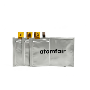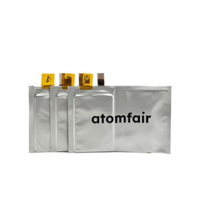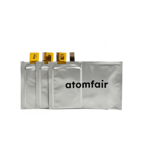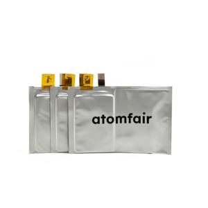
Description
ATOMFAIR 1.2 Ah Ni90 Si/C1100 Anode Dry Pouch CellRESEARCH GRADE CELL ARCHITECTURE
|
|||||||||||||||||||||||||||||||||||||||||||||||||||||||||
|
|||||||||||||||||||||||||||||||||||||||||||||||||||||||||
ATOMFAIR 1.2 Ah Ni90 Si/C1100 Anode Dry Pouch Cell – Technical Specifications and Handling Constraints – Handling
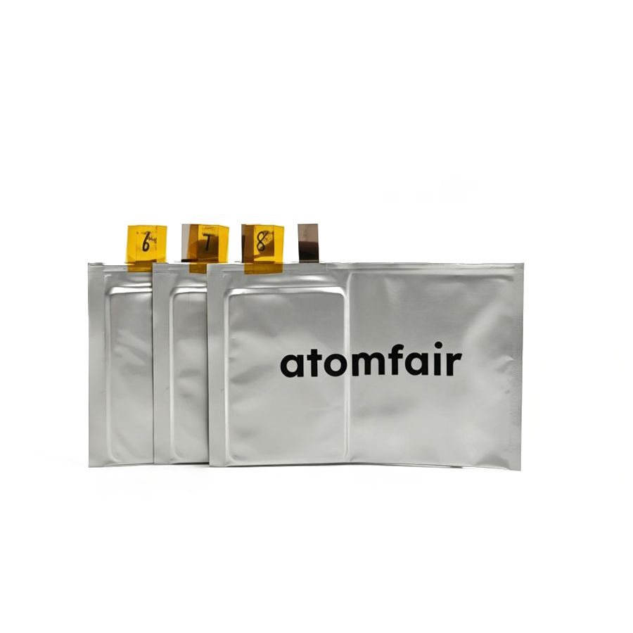
This document outlines the technical specifications and handling constraints for the ATOMFAIR 1.2 Ah Ni90 Si/C1100 dry pouch cell. The cell is a research-grade lithium-ion device without electrolyte, designed for high-fidelity benchmarking and electrolyte screening.
- Voltage Operating Window Constraint: Operate the cell strictly within the 2.3 V to 4.2 V voltage window to prevent overcharge or overdischarge damage.
- Negative-to-Positive Capacity Ratio: The NP ratio of 1.133 provides a safety margin for silicon anode expansion; do not exceed the rated capacity of 1.2 Ah.
- Storage Atmosphere Requirement: Store the dry pouch cell in an inert atmosphere glovebox to avoid moisture and oxygen contamination.
- Separator Ceramic Coating: The 2 μm Al₂O₃ ceramic coating on the 12 μm PE separator enhances thermal stability and prevents internal shorts.
Does the NP ratio of 1.133 in the Atomfair Ni90-Si/C1100 cell prioritize silicon swelling containment over full anode capacity utilization?
Yes, the NP ratio of 1.133 is an optimized balancing matrix specifically designed for silicon expansion safety, as stated in the technical specifications. The Si/C1100 anode baseline specific capacity of 1100 mAh/g is deliberately underutilized to maintain a nominal 1.2 Ah cell capacity, ensuring volumetric growth is managed during cycling. This trade-off prioritizes dimensional stability over maximizing capacity delivery from the anode.
What electrolyte compatibility constraints apply to this dry pouch cell for silicon anode gas evolution studies?
The cell is an un-functionalized dry unit supplied without electrolyte, requiring custom filling for gas evolution tracking. The separator features a 12 μm PE base layer with a 2 μm Al2O3 ceramic coating, which may limit wetting with high-viscosity or poorly wetting electrolytes. Researchers must validate electrolyte penetration and chemical compatibility with the ceramic coating to avoid compromised gas evolution measurements.
What activation voltage window and electrode alignment tolerances are required to achieve the nominal 1.2 Ah capacity?
The cell must be activated within the target voltage window of 2.3 V to 4.2 V to reach the 1.2 Ah nominal baseline capacity after proper electrolyte filling. Precise electrode alignment is critical: the cathode footprint of 45.5 mm x 64 mm must be centered within the larger anode footprint of 46.5 mm x 65 mm to prevent edge plating. The 6/7 laminated multi-layer stack requires careful handling during assembly to maintain electrode registry.
This dry pouch cell pairs a 203 mAh/g Ni90 cathode with a 1100 mAh/g Si/C1100 anode in a 6/7 layer stack, enabling high-fidelity benchmarking of silicon-compatible electrolytes and swelling behavior, though it requires end-user electrolyte infusion and careful formulation management.
✅ Pros
- High-capacity Si/C1100 anode: The 1100 mAh/g silicon-carbon composite anode provides an elite capacity horizon for evaluating next-generation electrolyte systems and expansion dynamics.
- Optimized NP ratio and separator: A negative-to-positive capacity ratio of 1.133 combined with a 12 μm PE + 2 μm Al₂O₃ ceramic-coated separator is explicitly designed to accommodate silicon expansion and improve safety during cycling.
❌ Cons
- Dry state requires electrolyte filling: The cell is assembled without liquid electrolyte infusion; the researcher must perform this step, introducing variability and demanding precise wetting protocols.
- Si/C anode demands compatible electrolytes: The high-capacity silicon-carbon anode is sensitive to electrolyte chemistry; improper formulation can exacerbate volumetric swelling and gas evolution, complicating data interpretation.