🌐 Foreword: The Conflict Between Anionic Redox and High-Voltage Interfaces
Lithium-Rich Manganese-Based (LMR) cathodes, utilizing both cationic and anionic redox mechanisms, can release extreme specific capacities exceeding 300 mAh/g. This makes them the critical pathway for achieving ultra-high energy densities of 450 Wh/kg and beyond.
However, the high cut-off voltage required to activate anionic activity (2.0V – 4.8V) causes conventional electrolytes to undergo violent oxidative decomposition at the cathode surface. Furthermore, the lattice oxygen evolution accompanying LMR cycling further catalyzes electrolyte failure. This issue explores the evolution of interfacial stability in LMR || Li systems under extreme 4.8V conditions.
📊 Performance Deconstruction: Electrochemical Behavior Under Ultra-High Loading
This experiment utilized industrial-grade 1 Ah pouch cells under extreme stress testing with a high areal mass loading of 27 mg/cm²:
1. Reaching the Limits of Theoretical Capacity
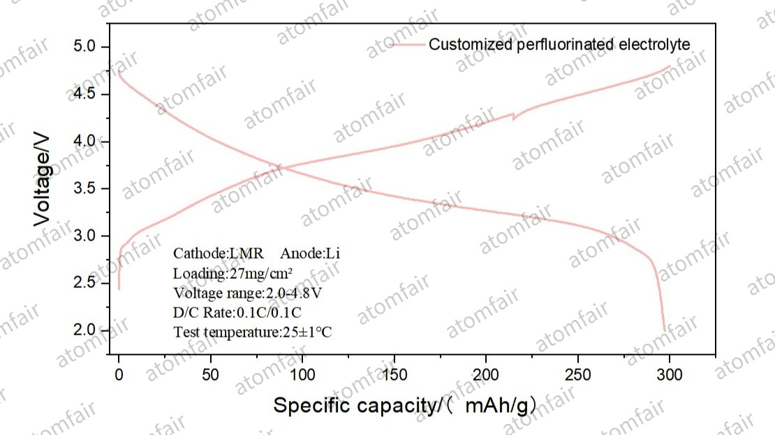
- Energy Density Benchmark: Within a 2.0V – 4.8V window, the system achieved a cell-level energy density of 460 Wh/kg.
- Specific Capacity Utilization: Empirical data shows that the LMR cathode, when paired against Lithium-Copper (LiCu) and pure Lithium (Li) anodes, released specific capacities of 288.76 mAh/g and 297.27 mAh/g, respectively. GCD curves indicate that the system maintains high voltage plateaus and kinetic stability even in states of deep delithiation.
2. The “Watershed” of Electrolyte Oxidative Resistance
In high-voltage LMR systems, the oxidation potential of the electrolyte dictates the ceiling of cycle life:
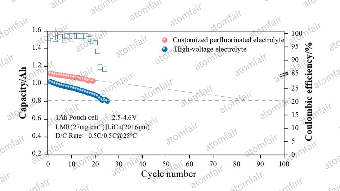
- Standard High-Voltage Solution (Blue): Limited by the high HOMO energy levels of the solvent molecules, interfacial impedance surges at 4.6V, leading to a severe capacity “plunge” around the 20th cycle.
- Customized Perfluorinated Electrolyte (Red): By utilizing fluorinated solvents to construct a strongly electronegative solvation shell, the dehydrogenation and decomposition of solvent molecules at LMR active sites are effectively suppressed. Although the system still exhibits decay under the extreme load of 460 Wh/kg, its effective cycling span is significantly superior to conventional high-voltage systems.
💡 Deep Insight: How Perfluorination Delays “Interfacial Collapse”
In 4.8V ultra-high voltage environments, LMR failure typically stems from the coupling effect of lattice oxygen evolution and electrolyte oxidation:
- Electronic Structure Remodeling: Our customized perfluorinated electrolyte significantly reduces oxidative sensitivity. It remains relatively inert even when exposed to high-valence transition metal ions and reactive oxygen species on the LMR surface.
- Induced Formation of Inorganic CEI: The perfluorinated components decompose preferentially on the cathode surface to form a dense, uniform LiF-rich Cathode Electrolyte Interphase (CEI). This layer acts as both a physical barrier and an ionic tunnel, slowing the accumulation of side reactions caused by lattice oxygen loss.
- Life Expectancy Analysis: Based on current capacity decay slopes, this protocol is projected to exceed 80 cycles while maintaining 80% capacity retention. This provides critical technical support for transitioning high-energy LMR pouch cells from “laboratory data” to “prototype validation.”
🛠️ Technical Specifications Benchmarking
- Cathode System: High-Capacity LMR (27 mg/cm²)
- Anode System: Composite Lithium-Copper (LiCu) / Pure Lithium Foil (Li)
- Cut-off Voltage: 2.0V – 4.8V
- Core Variable: Perfluorinated Electrolyte (Customized)
- Measured Energy Density: 460 Wh/kg (1 Ah Pouch Cell)