Description
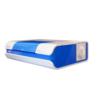
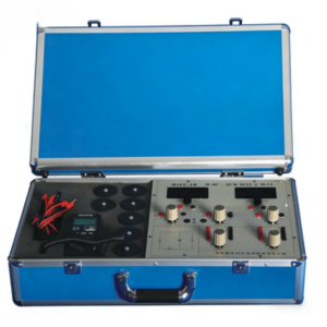
Atomfair EOM-739 Crystal Electro-Optic Modulation Tester
Product Overview
The Atomfair EOM-739 Crystal Electro-Optic Modulation Tester belongs to the optoelectronics and laser category. Based on the principle of the transverse electro-optic effect of crystals, this product leverages the phenomenon where an electric field induces a change in the refractive index of a crystal—known as the electro-optic effect. By adopting the typical LiNbO₃ crystal, it enables users to master the principles and experimental methods of crystal electro-optic modulation. With a simple experimental setup, users can measure the half-wave voltage and electro-optic constant of the crystal, observe the changes in the crystal’s optical properties caused by the electro-optic effect as well as the interference phenomenon of convergent polarized light, and conduct laser communication demonstration experiments.
Key Features
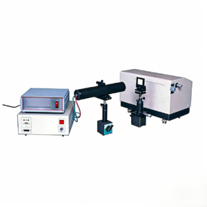
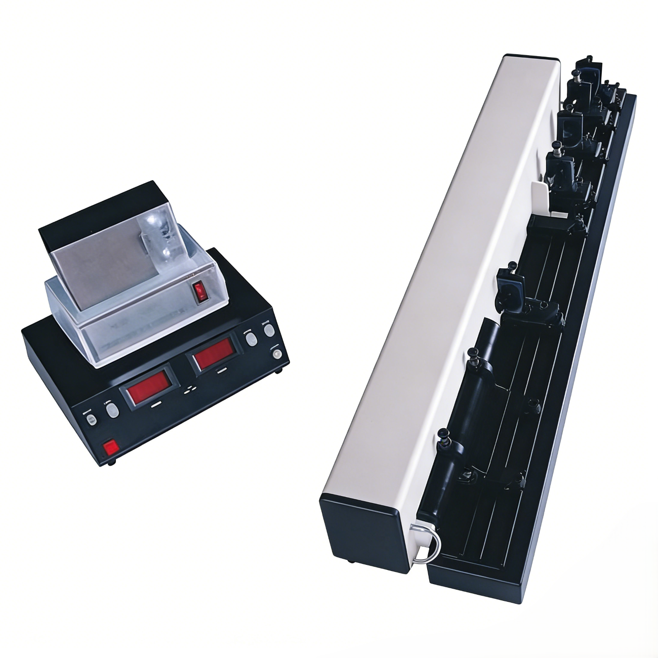
- Equipped with an aluminum alloy guide rail, the sliding seat and adjustment frame allow for precise optical path adjustment, ensuring the accuracy of experimental operations.
- Compatible with a digital dual-trace oscilloscope (optional), it can intuitively display and measure electro-optic modulation waveforms, facilitating experimental observation and data acquisition.
- The photoelectric receiver boasts high sensitivity and stable output waveforms, guaranteeing the reliability and accuracy of experimental results.
Experimental Contents
- Display electro-optic modulation waveforms and intuitively observe electro-optic modulation phenomena.
- Measure the half-wave voltage of the electro-optic crystal and further calculate the electro-optic constant.
- Conduct electro-optic modulation optical communication demonstration experiments to gain an in-depth understanding of relevant application scenarios.
Basic Configuration and Specifications
| Item No. | Name | Specifications |
|---|---|---|
| 1 | Helium-Neon Laser | Central wavelength: 632.8nm; Output power: 1.5mW |
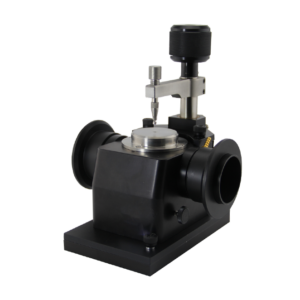
| 2 | LiNbO₃ Crystal | Electrodes: X-plane silver-plated electrodes; Flatness: <λ/8@632.8nm; Transmittance range: 420~5200nm |
| 3 | Polarizer | Light-transmitting aperture: 16mm; Wavelength range: 400-700nm; Polarization degree: 99.98%; Transmittance: 30% (parallel), 0.0045% (vertical) |
| 4 | Optical Components | Glan prism (8mm), λ/4 wave plate (10mm), ground glass plate |
| 5 | Electro-Optic Modulation Cabinet | Output sine wave modulation amplitude: 0-300V continuously adjustable; Output DC bias voltage: 0-600V continuously adjustable; Output frequency: 1kHz |
| 6 | Photoelectric Receiver | PIN photocell |
| 7 | Rotating Frame | Minimum scale: 1° |
| 8 | Optical Guide Rail | Length: 1m; Material: Hard aluminum profile |
| 9 | Other Accessories | 4-axis adjustment frame, beam collimation hole, active speaker |
Note: The configuration and parameters listed above are for reference only. Please refer to the packing list for the actual specifications, as minor changes will not be notified separately.
If you’re interested, have any questions, or have specific customization requirements, please feel free to contact us at inquiry@atomfair.com.