Recommended products
-
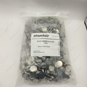
Atomfair 60 pcs of Al-Clad Stainless Steel 304SS CR2032 Coin Cell Cases for High Voltage Battery Research
$245.95 -
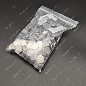
Atomfair Battery Cases 304SS CR2032 Coin Cell Case Sets (Case, Spring and Spacer) for Battery Research, pack of 100 sets
$129.95 -
Atomfair Cathode/Anode Al-Clad Stainless Steel 304SS CR2032 Coin Cell Cases for High Voltage Battery Research, 60 pcs/pk
$299.95 -
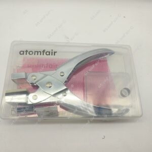
Atomfair Handheld Coin Cell Electrode Punch
Price range: $99.95 through $105.95 -
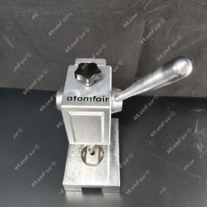
Atomfair High Precision Coin Cell Disc Cutting Machine for Electrode Sheet and Separator
$1,799.95 -

Two-Electrode Swagelok-Type Cells For Lab Coin Cell Testing TC4/304 Stainless Steel
Price range: $129.95 through $149.95 -
Atomfair Meshed CR2032 Coin Cell Cases
Coin Cell Casing Types and Specifications
Standard Coin Cell Sizes and Dimensions
Common Coin Cell Designations and Their Physical Dimensions
Standard coin cell batteries are widely used in consumer electronics, medical devices, and research applications due to their compact size and reliable performance. These cells follow standardized designations and dimensions established by international organizations to ensure compatibility and interchangeability. The most common naming convention includes prefixes such as “CR” for lithium manganese dioxide cells, followed by a four-digit number indicating dimensions. For example, in CR2032, the first two digits (20) represent the diameter in millimeters, and the last two digits (32) denote the thickness in tenths of a millimeter.
The International Electrotechnical Commission (IEC) and the American National Standards Institute (ANSI) are key organizations responsible for standardizing coin cell sizes. The IEC publishes specifications under the IEC 60086 series, while ANSI adheres to its own standards, often aligning with IEC guidelines. These standards emerged in the late 20th century as the demand for portable power sources grew, necessitating uniformity across manufacturers.
Common coin cell sizes and their dimensions include: – CR2032: 20.0 mm diameter, 3.2 mm thickness – CR2025: 20.0 mm diameter, 2.5 mm thickness – CR2016: 20.0 mm diameter, 1.6 mm thickness – LR44 (alkaline equivalent): 11.6 mm diameter, 5.4 mm thickness
Variations in size directly impact energy capacity and application suitability. Thicker cells like the CR2032 offer higher capacity, making them ideal for power-hungry devices such as computer motherboards, while thinner variants like the CR2016 are used in compact devices like car key fobs. Researchers must select appropriate sizes based on spatial constraints and energy requirements in experimental setups.
Standardization ensures that cells from different manufacturers remain interchangeable, reducing supply chain complexities. Deviations from these dimensions can lead to compatibility issues, emphasizing the importance of adhering to established norms in both commercial and research settings. The historical development of these standards reflects the broader trend toward global harmonization in battery technology, enabling seamless integration across industries.
Tolerances and Manufacturing Variations in Coin Cell Sizes
Standard coin cell sizes, such as those defined by the International Electrotechnical Commission (IEC) or other industry standards, must adhere to strict dimensional tolerances to ensure compatibility with battery holders, devices, and research equipment. These tolerances typically range from ±0.05 mm to ±0.2 mm for critical dimensions like diameter, thickness, and electrode alignment. For example, a common CR2032 coin cell has a nominal diameter of 20.0 mm, with an allowable tolerance of ±0.2 mm, and a thickness of 3.2 mm, with a tolerance of ±0.1 mm. These specifications are critical for maintaining consistent electrical contact and mechanical stability in applications.
The primary reason for tight tolerances is to ensure reliable electrical connectivity and prevent poor contact resistance, which can lead to voltage drops or intermittent connections. Variations beyond the specified limits may cause cells to fit too loosely or too tightly in battery compartments, leading to unreliable performance or physical damage. In research settings, even minor deviations can skew electrochemical measurements, particularly in high-precision studies involving impedance spectroscopy or long-term cycling tests.
Manufacturing variations arise from tool wear, material inconsistencies, or process fluctuations during stamping and forming. For instance, excessive diameter tolerance can result in misalignment during crimping, increasing internal resistance or causing short circuits. Case studies have shown that cells with thickness variations exceeding ±0.15 mm exhibited inconsistent pressure on electrode stacks, leading to uneven electrolyte distribution and accelerated capacity fade.
Measurement methodologies for verifying tolerances include micrometer gauges for thickness and optical comparators for diameter. Industry benchmarks often reference IEC 60086-3 for standard cells, which defines acceptable ranges for commercial and industrial use. Research-grade applications may impose stricter internal tolerances, such as ±0.05 mm, to minimize experimental variability.
In one documented case, a batch of coin cells with diameter deviations of +0.25 mm (beyond the ±0.2 mm limit) caused intermittent contact in a multi-cell holder, resulting in erratic discharge curves. Corrective measures involved recalibrating the stamping dies to restore compliance. Such examples highlight the importance of adherence to dimensional standards in both manufacturing and research contexts.
Precision in coin cell dimensions directly impacts reproducibility in battery testing. Laboratories conducting comparative studies often screen cells for dimensional compliance before use to eliminate outliers. Automated assembly systems further enforce consistency by rejecting units that fall outside predefined thresholds. The relationship between tolerances and performance underscores the need for rigorous quality control in both production and experimental workflows.
Applications and Selection Criteria Based on Coin Cell Dimensions
The selection of coin cell dimensions is a critical factor in determining their suitability for specific applications, as size directly impacts capacity, energy density, and compatibility with device constraints. Researchers must carefully evaluate trade-offs between these parameters to optimize performance for wearable electronics, medical implants, and other compact technologies.
Standard coin cell sizes, such as CR2032 (20 mm diameter, 3.2 mm height) or CR1216 (12.5 mm diameter, 1.6 mm height), are defined by IEC standards and offer varying capacities. Larger cells, like the CR2032, provide higher capacities (typically 220–240 mAh) due to greater electrode volume, making them suitable for applications requiring extended runtime, such as backup power or low-power sensors. Smaller cells, like the CR1216, offer reduced capacity (around 25 mAh) but enable ultra-thin designs for wearables or implantable medical devices where space is constrained.
Energy density, expressed in Wh/cm³, is influenced by cell dimensions. Thinner cells often exhibit lower energy density due to proportionally higher casing-to-volume ratios, which reduce active material content. For example, a CR2016 (20 mm diameter, 1.6 mm height) may have half the capacity of a CR2032 despite only a 50% reduction in height, highlighting the non-linear relationship between size and performance.
When selecting a coin cell, researchers should consider: 1. Device Volume Constraints: Wearables and medical implants often prioritize minimal thickness, favoring smaller cells like the CR1025 (10 mm diameter, 2.5 mm height). 2. Capacity Requirements: High-drain applications, such as wireless transmitters, may necessitate larger cells like the CR2450 (24.5 mm diameter, 5.0 mm height) for sufficient energy storage. 3. Mechanical Stability: Thicker casings in larger cells improve durability but increase weight, which may be unsuitable for flexible wearables.
A comparison of common coin cell sizes and their properties:
| Cell Type | Diameter (mm) | Height (mm) | Typical Capacity (mAh) |
|---|---|---|---|
| CR1216 | 12.5 | 1.6 | 25 |
| CR2032 | 20 | 3.2 | 220–240 |
| CR2450 | 24.5 | 5.0 | 550–620 |
In summary, the optimal coin cell size depends on balancing dimensional limitations with energy needs. Researchers should prioritize thinner cells for space-critical applications and larger cells when capacity outweighs size constraints. Understanding these trade-offs ensures efficient integration into target devices without compromising performance.
Material Composition and Properties of Casings
Metallic Alloys Used in Coin Cell Casings
Metallic alloys play a critical role in the performance and reliability of coin cell casings, with stainless steel, nickel-plated steel, and aluminum alloys being the most commonly used materials. Each alloy offers distinct properties that influence battery performance, longevity, and compatibility with other cell components.
Stainless steel, particularly grades 304 and 316, is widely used due to its excellent corrosion resistance and mechanical strength. The chromium content in stainless steel forms a passive oxide layer that protects against electrolyte degradation, making it suitable for aggressive chemistries. However, its electrical conductivity is lower than other metals, which can introduce minor resistive losses in high-current applications. Stainless steel is often preferred for long-term stability in lithium-based cells where electrolyte compatibility is crucial.
Nickel-plated steel combines the cost-effectiveness of mild steel with the enhanced corrosion resistance provided by the nickel coating. The plating thickness typically ranges from 2 to 10 micrometers, offering a balance between conductivity and durability. While not as corrosion-resistant as stainless steel, nickel-plated steel performs well in moderately aggressive environments and is commonly used in alkaline and zinc-air coin cells. The trade-off lies in its susceptibility to pitting corrosion if the nickel layer is compromised.
Aluminum alloys, such as 3003 or 8000 series, are favored for their lightweight properties and high electrical conductivity. Aluminum naturally forms a protective oxide layer, providing adequate corrosion resistance for non-aqueous electrolytes like those in lithium-ion cells. However, aluminum is less mechanically robust than steel and may deform under high crimping pressures. Its use is often limited to applications where weight savings and conductivity outweigh strength requirements.
Industry standards, such as IEC 60086 and ANSI C18.1, provide guidelines for material selection based on cell chemistry and operating conditions. Stainless steel is often specified for high-reliability applications, while nickel-plated steel offers a cost-effective alternative for consumer-grade cells. Aluminum alloys are selected when minimizing weight is critical. The choice depends on balancing corrosion resistance, mechanical integrity, conductivity, and cost for the intended application.
Polymer and Composite Materials for Specialty Casings
Polymer and composite materials are increasingly used in specialty coin cell casings due to their unique properties, which address limitations of traditional metallic casings. Among these materials, polyether ether ketone (PEEK), polytetrafluoroethylene (PTFE), and ceramic-coated metals stand out for their thermal stability, chemical resistance, and mechanical adaptability. These materials are particularly valuable in high-temperature or corrosive environments where standard metallic casings may fail.
PEEK exhibits exceptional thermal stability, maintaining structural integrity at temperatures up to 250°C. Its high mechanical strength and resistance to organic solvents make it suitable for aggressive electrochemical environments. PEEK casings are often used in lithium-sulfur and solid-state batteries, where prolonged exposure to reactive species occurs. However, PEEK’s high cost and challenging machining requirements limit widespread adoption.
PTFE is renowned for its chemical inertness, with near-universal resistance to acids, bases, and organic compounds. Its low friction coefficient and flexibility allow for tight seals without additional gaskets. PTFE can operate continuously at temperatures up to 260°C, making it ideal for high-temperature battery testing. A drawback is its lower mechanical strength compared to metals or PEEK, requiring thicker casing designs to prevent deformation under pressure.
Ceramic-coated metals combine the structural benefits of metal with the chemical resistance of ceramics. Aluminum or stainless steel substrates coated with alumina or zirconia provide a barrier against electrolyte corrosion while retaining high thermal conductivity. These casings are used in sodium-ion and high-voltage lithium-ion cells, where electrolyte decomposition risks are elevated. The coating process must ensure uniform thickness to avoid microcracks, which compromise performance.
Manufacturing these materials involves precision molding or machining, often requiring specialized equipment. PEEK and PTFE are typically injection-molded, while ceramic coatings are applied via plasma spraying or chemical vapor deposition. Tolerances must be tightly controlled to ensure proper crimping and sealing during cell assembly.
Compared to metallic casings, these materials offer superior corrosion resistance and thermal performance but may lack the same mechanical rigidity or conductivity. Their selection depends on specific application requirements, balancing cost, durability, and environmental conditions.
Surface Treatments and Coatings for Enhanced Performance
Surface treatments and coatings play a critical role in enhancing the performance and longevity of coin cell casings. These modifications address key challenges such as corrosion, interfacial resistance, and thermal management, ensuring stable operation across diverse battery chemistries and environmental conditions.
Anodization is a widely used electrochemical process that forms a controlled oxide layer on aluminum or titanium casings. This layer improves corrosion resistance by acting as a barrier against electrolyte decomposition and moisture ingress. The thickness of the anodized layer typically ranges from 5 to 25 micrometers, depending on voltage and electrolyte composition. Hard anodization further enhances wear resistance, making it suitable for high-stress applications.
Passivation is another surface treatment, often applied to stainless steel casings, where a thin chromium oxide layer forms naturally or through chemical treatment. This passive film minimizes ionic leaching and reduces galvanic corrosion, particularly in cells using aggressive electrolytes. The effectiveness of passivation depends on the alloy composition and exposure conditions, with optimized treatments achieving corrosion rates below 0.1 millimeters per year in accelerated testing.
Conductive polymer coatings, such as poly(3,4-ethylenedioxythiophene) (PEDOT), are applied to improve interfacial conductivity between the casing and electrode materials. These coatings reduce contact resistance by up to 50%, enhancing power delivery in high-rate applications. Deposition methods like chemical vapor deposition (CVD) or physical vapor deposition (PVD) enable precise control over coating thickness and uniformity. For instance, PEDOT layers deposited via CVD exhibit consistent coverage at thicknesses below 1 micrometer, maintaining mechanical flexibility while preventing delamination.
Thermal management coatings, including ceramic-based materials like aluminum oxide or zirconia, are applied via plasma spraying or atomic layer deposition (ALD). These coatings dissipate heat more efficiently, reducing thermal hotspots during fast charging or high-load cycles. ALD-deposited films as thin as 100 nanometers can improve thermal conductivity by 20% without compromising casing integrity.
The choice of deposition method significantly impacts durability. PVD and CVD provide dense, adherent coatings ideal for high-cycle applications, whereas spray-coated layers may require post-treatment for optimal performance. Accelerated aging tests demonstrate that CVD-coated casings retain over 90% of their initial protective properties after 500 cycles, outperforming untreated counterparts.
By tailoring surface treatments to specific operational demands, manufacturers can extend coin cell lifespan while maintaining electrochemical stability. Advances in deposition techniques continue to refine these coatings, enabling thinner, more efficient layers that meet evolving energy storage requirements.
Specialty and Custom Coin Cell Casings
Hermetically Sealed and High-Pressure Coin Cell Casings
Hermetically sealed and high-pressure coin cell casings are critical for advanced battery research, particularly in applications requiring extreme environmental stability or operation under non-atmospheric conditions. These specialized casings are engineered to maintain integrity under high internal pressure, vacuum, or corrosive environments, where standard casings would fail. The design and material selection are tailored to meet stringent performance criteria, ensuring reliability in demanding experimental or industrial settings.
Stainless steel is a common choice for high-pressure casings due to its mechanical strength and corrosion resistance. Grades such as 316L are preferred for their low carbon content and resistance to electrochemical degradation. Titanium casings offer superior strength-to-weight ratios and exceptional resistance to oxidation, making them suitable for lithium-air batteries where exposure to reactive oxygen species is a concern. Ceramic composites, including alumina or zirconia, provide excellent thermal and electrical insulation, crucial for solid-state batteries operating at elevated temperatures.
Achieving a reliable hermetic seal under high pressure or vacuum presents significant engineering challenges. The casing must withstand mechanical stress without deformation, while the seal must prevent gas or liquid leakage over extended periods. Laser welding and cold welding techniques are often employed to create robust seals without introducing contaminants. The joint design, including stepped or grooved interfaces, enhances sealing effectiveness by distributing mechanical load evenly.
Leak-proof integrity is verified through helium mass spectrometry or pressure decay testing. These methods detect minute leaks with sensitivities as low as 1×10^-9 mbar·L/s, ensuring compliance with stringent standards. Accelerated aging tests simulate long-term exposure to harsh conditions, validating the casing’s durability.
In advanced battery research, these casings enable studies on lithium-air systems, where oxygen permeability must be controlled, and solid-state batteries, where interfacial stability is paramount. Their use extends to high-energy-density prototypes requiring precise pressure management or inert atmospheres. By addressing the limitations of standard casings, hermetically sealed and high-pressure designs facilitate breakthroughs in next-generation energy storage technologies.
Custom-Shaped and Miniaturized Coin Cell Casings
Custom-shaped and miniaturized coin cell casings address the growing demand for energy storage solutions in applications where conventional cylindrical cells are impractical. These unconventional designs include rectangular, prismatic, and ultra-thin geometries, tailored to fit within tightly constrained spaces. Wearable electronics, medical implants, and IoT devices often require such form factors to integrate seamlessly without compromising performance or ergonomics.
Manufacturing these casings involves specialized processes to achieve precise dimensions and structural integrity. Deep drawing and precision stamping are common methods for forming thin, complex shapes from metals like stainless steel or titanium. Ultra-thin designs, with thicknesses below 0.3 mm, require controlled annealing to prevent material stress during shaping. For prismatic or rectangular casings, laser cutting and micro-welding ensure tight tolerances and hermetic sealing, critical for preventing electrolyte leakage in miniaturized cells.
Material selection presents unique challenges for non-standard geometries. While standard coin cells rely on uniform stress distribution in circular designs, custom shapes introduce uneven mechanical loads. High-strength alloys or laminated composites are often used to counteract deformation during crimping and operation. For example, titanium casings offer superior strength-to-weight ratios for medical implants, while aluminum-polymer laminates enable flexible, lightweight solutions for wearables.
Maintaining structural integrity during assembly is critical. Custom crimping tools with adaptive dies accommodate irregular shapes, ensuring uniform pressure without casing rupture. Electrode placement must also account for asymmetric geometries to prevent internal short circuits. In ultra-thin cells, separator materials with high puncture resistance are essential to withstand mechanical stress during cycling.
Applications demanding these casings include hearing aids, smart patches, and microsensors, where space optimization is paramount. The ability to conform to device-specific layouts without sacrificing energy density makes custom coin cells indispensable in next-generation portable and implantable technologies.
Corrosion-Resistant and Chemically Inert Coin Cell Casings
Corrosion-resistant and chemically inert coin cell casings are critical for battery research involving aggressive electrochemical environments, such as aqueous electrolytes, highly acidic or alkaline solutions, or reactive chemistries like lithium-metal systems. These specialized casings prevent unwanted side reactions, electrolyte decomposition, and structural degradation, ensuring reliable electrochemical measurements and long-term cell stability.
Nickel-plated steel is a widely used material due to its balance of cost and performance. The nickel layer provides a barrier against oxidation and corrosion, particularly in mildly acidic or alkaline conditions. However, in highly corrosive environments, such as concentrated sulfuric acid or strong bases, nickel-plated casings may still degrade over time. For improved resistance, gold-coated casings offer superior inertness, as gold is unreactive to most electrolytes. The gold layer prevents ion migration and surface oxidation, making it ideal for sensitive measurements in extreme pH conditions or high-voltage applications.
Polymer laminates, such as PEEK or PTFE-based composites, are another alternative for highly corrosive settings. These materials are inherently non-conductive and chemically inert, resisting attack from aggressive solvents and acids. Laminated casings often incorporate conductive layers to maintain electrical contact while isolating the cell internals from external degradation.
Testing protocols for these casings involve accelerated aging in target electrolytes, followed by electrochemical impedance spectroscopy (EIS) and surface analysis (e.g., SEM/EDS) to detect corrosion products or delamination. Long-term stability tests may include cyclic voltammetry under harsh conditions to assess performance degradation over hundreds of cycles. Weight loss measurements after immersion in corrosive media provide quantitative data on material dissolution rates.
Key considerations when selecting corrosion-resistant casings include compatibility with the electrolyte, mechanical durability under crimping forces, and thermal stability. For example, polymer laminates may deform under high pressure, while metallic coatings must maintain adhesion during cell assembly. Researchers must validate casing performance under realistic operating conditions to ensure data integrity in aggressive electrochemical studies.
Proper Usage of Coin Cells in Battery Research
Electrode Preparation and Loading Techniques
Slurry Formulation and Coating Methods for Electrodes
Slurry formulation and coating methods are critical steps in preparing electrodes for coin cell assembly. The quality of the slurry and the uniformity of the coating directly influence electrode performance, including capacity, cycle life, and rate capability.
The electrode slurry consists of several key components. Active materials, such as lithium metal oxides or graphite, provide the electrochemical capacity. Binders, like polyvinylidene fluoride (PVDF) or carboxymethyl cellulose (CMC), ensure mechanical integrity and adhesion to the current collector. Conductive additives, such as carbon black or carbon nanotubes, enhance electrical conductivity. Solvents, including N-methyl-2-pyrrolidone (NMP) or water, dissolve the binder and disperse the components uniformly.
Slurry viscosity must be carefully controlled to ensure proper coating and adhesion. Low viscosity can lead to uneven deposition, while high viscosity may cause cracking during drying. Homogeneity is essential to prevent agglomeration of particles, which can result in poor electrochemical performance. Stability is another critical factor; slurries should remain well-dispersed without settling or phase separation before coating.
Common coating techniques include doctor blade, slot-die, and spray coating. Doctor blade coating is widely used in research due to its simplicity and low cost. A blade spreads the slurry over a substrate at a fixed gap, typically between 50 and 500 micrometers. The coating thickness depends on the gap height, slurry viscosity, and blade speed. However, this method may produce uneven edges and requires careful optimization.
Slot-die coating offers better precision and uniformity, making it suitable for large-scale production. The slurry is pumped through a narrow slot onto a moving substrate, allowing precise control over thickness and width. Parameters such as flow rate, substrate speed, and gap distance must be optimized to avoid defects like streaks or bubbles.
Spray coating is useful for depositing thin or patterned layers. The slurry is atomized into fine droplets and sprayed onto the substrate. This method allows for flexible design but may require multiple passes to achieve sufficient loading and uniformity.
Drying protocols are crucial to prevent cracking or delamination. Slow drying at moderate temperatures (60-100°C) helps evaporate solvents uniformly without inducing stress. Rapid drying can cause binder migration, leading to poor adhesion or cracking. Proper drying ensures a dense, crack-free electrode film with good mechanical stability.
In summary, slurry formulation and coating methods require careful optimization of materials, viscosity, and processing parameters to produce high-quality electrodes for coin cell research. Each coating technique has advantages and limitations, and selecting the appropriate method depends on the desired electrode properties and scale of production.
Electrode Calendering and Density Optimization
Electrode calendering is a critical step in coin cell research, directly influencing electrode performance by optimizing particle contact and reducing porosity. The process involves compressing the electrode material between rollers to achieve a uniform thickness and higher density. Enhanced particle contact improves electronic conductivity, while reduced porosity minimizes ionic resistance, leading to better overall electrochemical performance.
Roll presses are the primary equipment used for calendering. These machines apply controlled pressure to the electrode, ensuring consistent compaction. Key parameters affecting the outcome include pressure, roller speed, and temperature. Pressure typically ranges from 100 to 1000 MPa, depending on the active material and binder system. Higher pressure increases density but may compromise electrode flexibility. Roller speed must be optimized to prevent cracking or delamination, often kept between 0.1 to 1 m/min. Temperature control is essential for materials sensitive to heat, as excessive heat can degrade binders or alter electrode morphology.
Electrode density is measured using gravimetric and volumetric methods. Gravimetric density is calculated by dividing the electrode mass by its geometric volume, while volumetric density considers pore space. Optimal density balances mechanical integrity with electrolyte accessibility. Excessive compaction can hinder electrolyte penetration, reducing ion transport and increasing polarization. A typical target for lithium-ion electrodes ranges from 1.6 to 3.5 g/cm³, depending on the active material.
Trade-offs between density and electrolyte penetration must be carefully managed. Higher density improves energy density but may limit rate capability due to restricted electrolyte access. Researchers often perform porosity measurements using mercury intrusion porosimetry or gas adsorption techniques to ensure sufficient pore connectivity for electrolyte infiltration. A porosity range of 20-40% is commonly targeted for balanced performance.
Calendering parameters should be tailored to the specific electrode composition and cell requirements. Systematic testing with varying pressure and speed helps identify the optimal conditions without compromising structural integrity or electrochemical function. This approach ensures reproducible and high-performance electrodes for coin cell research.
Precision Electrode Cutting and Alignment Techniques
Precision in electrode cutting and alignment is critical for reliable coin cell performance. The process begins with cutting electrodes into uniform discs that match the coin cell casing dimensions. Common methods include punch dies, laser cutting, and manual punching, each with distinct advantages and limitations.
Punch dies offer high repeatability and clean edges, essential for minimizing defects that could lead to short circuits. Standard dies produce discs with tolerances within ±0.1 mm, ensuring consistent electrode dimensions. Edge quality is crucial; jagged or uneven edges increase the risk of tearing separator materials or causing internal shorts. Laser cutting provides superior precision, capable of achieving tolerances as tight as ±0.05 mm, with minimal burring. However, thermal effects from laser cutting may alter electrode material properties near the edges, requiring careful parameter optimization. Manual punching is less precise but suitable for prototyping, though it risks deformation if excessive force is applied.
Alignment during stacking is equally important. Misaligned electrodes can lead to uneven current distribution, reduced capacity, or internal shorts. Proper alignment ensures full contact between layers while maintaining separator integrity. Tools such as alignment jigs help position electrodes concentrically within the casing. These jigs often feature guide pins or recessed slots to center the electrode disc before stacking additional layers. Microscopes or magnifying lenses aid in visual verification, particularly for thin or fragile electrodes where minor deviations can compromise performance.
For multi-layer configurations, maintaining alignment throughout stacking is critical. Even a 0.2 mm offset can create localized stress points, increasing the risk of separator puncture. Some researchers use transparent temporary holders to verify layer alignment before final assembly. The use of non-conductive spacers can further assist in maintaining consistent spacing between electrodes.
Material handling also plays a role. Electrodes should be cut and handled in a controlled environment to avoid contamination or physical damage. Cleanroom conditions or gloveboxes are preferred for sensitive materials. Static electricity can displace lightweight electrodes, so anti-static measures may be necessary during alignment.
Precision in these steps directly impacts cell performance, cycle life, and safety. Consistent electrode dimensions and alignment reduce variability in experimental results, ensuring reliable data for battery research.
Assembly Protocols for Different Cell Types
Standard CR2032 Coin Cell Assembly Protocol
Standard CR2032 coin cell assembly requires meticulous attention to detail to ensure consistent performance and reliability. Below is a step-by-step protocol covering electrode alignment, separator placement, electrolyte filling, and crimping, along with best practices and troubleshooting guidance.
Electrode Preparation and Alignment Begin with pre-dried electrodes, typically lithium metal as the anode and a cathode coated on a current collector. Electrode discs should be punched to 15.5 mm diameter for CR2032 cells, ensuring no frayed edges. The cathode must be centered on the bottom casing (positive terminal) with the active material facing upward. Misalignment can cause short circuits or uneven current distribution. Use non-metallic tweezers to handle electrodes to avoid contamination or damage.
Separator Placement A porous polypropylene or glass fiber separator (16-18 mm diameter) is placed over the cathode. The separator must fully cover the electrode to prevent direct contact between anode and cathode. Ensure it is flat and free of wrinkles, as folds may lead to localized pressure points or electrolyte dry spots. Pre-wetting the separator with a few drops of electrolyte (e.g., 1M LiPF6 in EC:DMC) improves ionic conductivity.
Electrolyte Filling Add electrolyte dropwise until the separator is saturated but without pooling. For CR2032 cells, 50-70 µL is typically sufficient. Excess electrolyte can cause leakage during crimping, while insufficient amounts lead to high impedance. Work in an argon-filled glovebox (O₂ and H₂O levels below 1 ppm) to prevent moisture-induced side reactions.
Anode Placement and Crimping Place the lithium anode (15.5 mm diameter) onto the separator with minimal delay to avoid oxidation. Align the top casing (negative terminal) and position it evenly. Use a manual or automated crimper with a force of 500-700 kgf to seal the cell. Under-crimping results in poor electrical contact, while over-crimping may deform the casing or breach the seal. Inspect the crimped edge for uniformity; a smooth, concentric ring indicates proper sealing.
Best Practices – Store materials in a dry environment before assembly. – Calibrate crimping tools regularly to maintain consistent pressure. – Verify electrolyte compatibility with electrode materials to avoid degradation.
Troubleshooting Common Errors – Short Circuits: Check for separator misplacement or metal debris. – High Impedance: Ensure proper electrolyte saturation and electrode contact. – Leakage: Reduce electrolyte volume or inspect crimp integrity.
Following these protocols ensures reproducible CR2032 coin cells with optimal performance for battery research.
High-Pressure Coin Cell Assembly for Solid-State Batteries
Assembling high-pressure coin cells for solid-state battery research requires specialized techniques to address the unique challenges posed by solid electrolytes. Unlike liquid electrolyte cells, solid-state systems demand precise control over interfacial contact and stack compression to minimize impedance and ensure stable performance. The following guide outlines key considerations and methods for high-pressure assembly.
The first critical step is optimizing interfacial contact between solid electrolyte and electrodes. Poor contact increases interfacial resistance, degrading cell performance. To mitigate this, apply uniform pressure during stacking. Use polished, flat electrodes and solid electrolyte pellets to reduce surface roughness. Pre-compression of individual layers before final assembly improves contact. A typical pre-compression pressure ranges from 100 to 300 MPa, depending on material properties.
Stack compression must be carefully controlled to avoid fracturing brittle solid electrolytes while maintaining sufficient pressure for ionic conduction. Hydraulic or mechanical presses are commonly used, with pressures between 200 and 500 MPa applied during crimping. The pressure must be evenly distributed to prevent localized stress concentrations. Shim spacers can help adjust stack height and ensure consistent pressure application.
Pressure maintenance after assembly is crucial. Unlike liquid cells, solid-state cells rely on sustained pressure to preserve interfacial integrity. Spring-loaded or screw-based fixtures are often integrated into custom casings to maintain pressure during cycling. These fixtures must resist relaxation over time to prevent performance decay.
Material handling differs significantly from liquid electrolyte cells. Solid electrolytes are sensitive to moisture and oxygen, requiring assembly in inert environments such as argon-filled gloveboxes. Contamination can lead to interfacial degradation, so handling tools and components must be thoroughly dried and pre-treated.
Sealing requirements are more stringent due to the absence of self-healing liquid electrolytes. Hermetic sealing is essential to prevent gas ingress or moisture penetration, which can degrade interfaces. Laser welding or cold welding techniques are preferred over standard crimping for enhanced seal integrity.
High-pressure coin cells demand precision in every step, from stack preparation to final sealing. By addressing these challenges with specialized techniques, researchers can achieve reliable solid-state battery performance.
Hermetically Sealed Coin Cells for Aqueous Electrolytes
Assembling hermetically sealed coin cells for aqueous electrolytes presents distinct challenges due to the reactivity of water with common battery materials and the need for rigorous moisture exclusion. The process demands careful selection of components and precise assembly techniques to prevent electrolyte leakage, corrosion, and premature cell failure.
Material Selection for Aqueous Compatibility The casing must resist corrosion from the electrolyte. Stainless steel (316L grade) is often used for its high resistance to chloride-induced pitting, while titanium casings offer superior performance in highly acidic or alkaline environments. Gaskets must be chemically inert; perfluoroelastomers (FFKM) or polytetrafluoroethylene (PTFE) are preferred due to their low water permeability and stability across a wide pH range.
Moisture Exclusion During Assembly Aqueous electrolytes require strict control of ambient humidity during assembly. Glove boxes with sub-ppm moisture levels (<1 ppm H2O) are essential. Pre-drying components at 80–100°C under vacuum for 12–24 hours removes residual moisture. Electrolytes should be prepared and stored in sealed containers with desiccants.
Sealing Techniques Laser welding provides a robust hermetic seal but requires precise parameter control to avoid thermal damage to the gasket. Typical settings for 316L stainless steel include a pulse energy of 3–5 J and a spot diameter of 0.2–0.5 mm. Epoxy encapsulation is an alternative for lower-throughput applications; two-part epoxy systems (e.g., epoxy-amine) with low shrinkage and high adhesion to metals are recommended. Cure schedules must balance speed and void formation—typically 60°C for 1–2 hours.
Case Studies of Failure Modes 1. Gasket Degradation: In a zinc-ion cell using alkaline electrolyte, FFKM gaskets showed swelling after 50 cycles due to hydroxide attack. Switching to PTFE-lined gaskets extended cycle life to 200 cycles. 2. Casing Corrosion: Aqueous Na-ion cells with mild steel casings exhibited pitting within 20 cycles. Upgrading to 316L stainless steel eliminated visible corrosion after 100 cycles. 3. Seal Failure: Laser-welded cells with improper energy settings developed microcracks, leading to electrolyte leakage within 10 cycles. Optimizing pulse energy and weld path overlap reduced failure rates by 90%.
Mitigation Strategies – Conduct accelerated aging tests in humid environments (85% RH, 85°C) to validate seal integrity. – Use dual-sealing approaches (e.g., laser weld + epoxy edge coating) for critical applications. – Implement real-time pressure monitoring during crimping to detect gasket misalignment or compression flaws.
By addressing these challenges through material science and precision engineering, hermetically sealed aqueous coin cells can achieve reliable performance comparable to non-aqueous systems.
Sealing Methods and Leak Prevention
Mechanical Crimping Techniques for Coin Cell Sealing
Mechanical crimping is a widely used method for sealing coin cells, ensuring a leak-proof and secure assembly. The process involves deforming the cell casing to create a tight seal between the can and the lid, preventing electrolyte leakage and maintaining internal pressure. Proper crimping requires precise force application, alignment, and tool selection to achieve consistent results.
The crimping process begins with placing the lid onto the filled cell can, ensuring proper alignment. The assembly is then subjected to radial force through a crimping tool, which deforms the can’s edge over the lid. Key parameters include crimping force, speed, and tool geometry. Typical crimping forces range between 50 N to 200 N, depending on casing material and thickness. Excessive force can cause over-crimping, leading to casing fractures or internal short circuits, while insufficient force may result in weak seals prone to leakage.
Tool selection depends on production scale and precision requirements. Manual crimping tools, such as hand presses with custom dies, are suitable for low-volume research applications. Automated crimping machines offer higher consistency and throughput for industrial use, often integrating force feedback systems to monitor quality. Alignment is critical; misaligned crimping can cause uneven pressure distribution, compromising seal integrity. Precision jigs or optical alignment systems mitigate this risk.
Material compatibility plays a significant role in crimp quality. Stainless steel casings, commonly used in lithium-based cells, require higher crimping forces due to their hardness compared to aluminum. The casing thickness, typically 0.1 mm to 0.3 mm, also influences the required force. Industry standards, such as IEC 60086-3, specify acceptable leakage rates and mechanical durability for crimped seals.
Common failure modes include burr formation, micro-cracks, and incomplete seals. Burrs arise from excessive tool wear or misalignment, while micro-cracks result from material fatigue during over-crimping. Regular tool maintenance and process validation minimize these issues. Force-displacement monitoring during crimping helps identify deviations before defective seals occur.
In summary, successful mechanical crimping relies on controlled force application, precise alignment, and appropriate tool selection. Understanding material properties and adhering to industry standards ensures reliable, leak-proof coin cell assemblies.
Gasket and O-Ring Sealing Systems in Coin Cells
Gasket and O-ring sealing systems play a critical role in coin cell assembly by preventing electrolyte leakage and gas escape, ensuring long-term performance and safety. These seals must maintain integrity under varying pressures, temperatures, and electrochemical conditions while resisting degradation from the electrolyte.
Materials used in these seals include PTFE (polytetrafluoroethylene) and elastomers such as nitrile rubber (NBR), fluorocarbon (FKM), and ethylene propylene diene monomer (EPDM). PTFE offers excellent chemical resistance, particularly against aggressive electrolytes like organic carbonates and lithium salts, but lacks elasticity, requiring precise compression to form an effective seal. Elastomers provide better flexibility and conformability, with FKM being highly resistant to swelling in organic electrolytes. NBR is cost-effective but may degrade in ester-based electrolytes, while EPDM performs well in alkaline environments but is less suitable for highly acidic or organic systems.
Design considerations for gasket and O-ring seals include compression ratios, groove geometry, and thermal stability. A compression ratio of 20-30% is typical for elastomeric O-rings to ensure sufficient contact pressure without excessive deformation. Groove geometry must accommodate seal expansion due to temperature fluctuations or electrolyte exposure. For static sealing applications, such as coin cell lids, square or rectangular grooves are common, while dynamic seals require rounded profiles to minimize friction. Thermal stability is crucial, as excessive heat can cause elastomers to harden or PTFE to creep, leading to seal failure. Most sealing materials operate reliably within -40°C to 150°C.
Static sealing is predominant in coin cells, where components remain fixed after assembly. Dynamic sealing, involving moving parts, is rare in standard coin cells but may apply in specialized designs. Static seals benefit from constant compression, whereas dynamic seals face wear and friction challenges. Limitations of gasket-based systems include pressure thresholds; elastomers typically withstand up to 10-20 MPa, while PTFE can handle higher pressures but may cold-flow over time. Additionally, prolonged exposure to electrolytes can cause swelling or embrittlement, necessitating careful material selection.
In summary, gasket and O-ring sealing systems are vital for coin cell integrity. Material compatibility, precise design, and environmental considerations determine their effectiveness, with each material offering distinct advantages and limitations based on application requirements.
Laser Welding and Hermetic Sealing for High-Performance Coin Cells
Laser welding has emerged as a critical technique for achieving hermetic seals in coin cells, particularly in applications requiring high energy density or operation in extreme environments. The process offers superior precision, speed, and reliability compared to traditional sealing methods, ensuring minimal gas leakage and long-term electrochemical stability.
Fiber lasers and pulsed lasers are the most commonly used types for coin cell sealing. Fiber lasers provide continuous wave output, enabling deep penetration and high-speed welding, while pulsed lasers deliver controlled energy bursts, reducing heat input and minimizing distortion. Optimal weld parameters depend on material thickness and composition but typically involve power settings between 50-300 W and pulse durations ranging from 0.5-10 ms. These parameters must be finely tuned to avoid defects such as porosity or incomplete fusion.
Joint design plays a crucial role in weld integrity. Lap joints are frequently used for their ease of alignment and robust mechanical strength, while butt joints require precise edge preparation but offer a more compact seal. The choice depends on the cell casing geometry and material compatibility. Post-weld inspections are essential to verify hermeticity, with helium leak testing being the gold standard due to its sensitivity to detect leaks as low as 1×10⁻⁹ mbar·L/s. X-ray imaging or ultrasonic testing may also be employed to identify internal defects.
Challenges in laser welding include managing heat-affected zones (HAZ), which can alter material properties and induce brittleness, particularly in thin casings. Proper parameter optimization and cooling strategies mitigate these effects. Additionally, dissimilar material welding, such as stainless steel to aluminum, requires careful control to prevent intermetallic formation.
Unlike mechanical crimping or gasket-based seals, laser welding eliminates the need for additional components, reducing weight and potential failure points. This makes it ideal for high-performance applications like aerospace or medical devices, where reliability is paramount. The technique’s non-contact nature also minimizes contamination risks, further enhancing cell longevity.
In summary, laser welding provides a robust solution for hermetic sealing in coin cells, balancing precision with efficiency. Its adaptability to various materials and joint configurations ensures widespread applicability in advanced battery research and industrial production.
Environmental and Safety Considerations
Handling and Storage Guidelines for Coin Cells
Proper handling and storage of coin cells are critical in battery research to ensure safety, longevity, and reliable performance. Coin cells, particularly lithium-based variants, pose risks such as short-circuiting, thermal runaway, and chemical leakage if mishandled. Adhering to established protocols minimizes hazards and preserves cell integrity.
Safe handling practices begin with preventing short-circuits. Always use insulated tools when manipulating coin cells, and avoid placing them on conductive surfaces. Short-circuiting can occur if the casing contacts both terminals simultaneously, leading to rapid heating or combustion. Wear appropriate personal protective equipment (PPE), including gloves and safety glasses, to shield against accidental exposure to electrolytes or reactive materials. Handle cells with care to avoid physical damage, such as punctures or dents, which may compromise the casing and lead to leaks.
Storage conditions significantly impact coin cell performance and shelf life. Ideal storage temperatures range between 10°C and 25°C, with relative humidity below 50%. Extreme temperatures accelerate degradation; sub-freezing conditions may cause electrolyte solidification, while high temperatures increase self-discharge rates. For long-term storage, maintain cells in a dry, inert environment, such as an argon-filled glovebox, to prevent moisture ingress and oxidation. Lithium-based cells are particularly sensitive to humidity and should never be exposed to ambient air for extended periods.
Shelf-life considerations depend on chemistry and storage conditions. Primary lithium coin cells typically retain 90% capacity for 10 years when stored properly. Rechargeable variants, such as lithium-ion, have shorter shelf lives due to gradual electrolyte decomposition. Regularly inspect stored cells for swelling, leakage, or voltage drops, and discard compromised units following hazardous waste disposal guidelines.
Hazardous materials in coin cells, such as lithium metal or toxic electrolytes, require strict precautions. OSHA mandates proper labeling and containment of reactive materials, while ISO 12405-3 outlines safety standards for lithium-ion battery storage. Never incinerate or disassemble cells, as this may release harmful substances. Dispose of spent cells through certified recycling programs compliant with local regulations.
By following these protocols, researchers can mitigate risks and ensure the safe use of coin cells in battery studies. Adherence to OSHA and ISO standards further reinforces a culture of safety and reliability in laboratory environments.
Disposal and Recycling Protocols for Spent Coin Cells
Spent coin cells, depending on their chemistry, are classified as hazardous or non-hazardous waste under regulatory frameworks such as the U.S. Environmental Protection Agency (EPA) and the European Union’s Registration, Evaluation, Authorisation, and Restriction of Chemicals (REACH). Proper disposal and recycling are critical to prevent environmental contamination and recover valuable materials.
Lithium-based coin cells (e.g., Li-MnO2, Li-SOCl2) are classified as hazardous due to their reactive components. The EPA mandates that these cells be disposed of through certified hazardous waste handlers to mitigate fire risks and toxic leakage. Alkaline coin cells (e.g., Zn-MnO2) are generally non-hazardous but still require recycling to reclaim zinc and manganese. Nickel-metal hydride (NiMH) cells contain recoverable rare-earth metals and are subject to recycling protocols under REACH.
Approved disposal methods vary by region. In the U.S., the Resource Conservation and Recovery Act (RCRA) outlines procedures for hazardous battery waste, including incineration in controlled facilities or secure landfill disposal with leak-proof containment. The EU’s Battery Directive enforces strict recycling targets, requiring manufacturers to fund collection and recycling programs.
Certified recycling facilities employ specialized processes for material recovery. Lithium cells undergo shredding and high-temperature treatment to separate lithium salts and metals. Alkaline cells are processed through mechanical separation to extract steel, zinc, and manganese compounds. NiMH cells are dismantled for nickel and rare-earth element recovery. These processes must comply with ISO 14001 environmental management standards.
Best practices for researchers include segregating spent cells by chemistry and using designated collection points. Many institutions partner with certified recyclers like Call2Recycle (U.S.) or Eurobat (EU) to ensure compliance. Documentation of waste streams is required under REACH and EPA regulations to track disposal and recycling outcomes.
Failure to adhere to regulations can result in penalties, including fines under the Toxic Substances Control Act (TSCA) or REACH enforcement measures. Researchers must stay informed on local and international guidelines to ensure environmentally responsible disposal of coin cells.
Mitigating Thermal Runaway and Fire Risks in Coin Cell Testing
Thermal runaway and fire hazards in coin cell testing present significant risks due to the high energy density and reactive materials involved. Understanding the causes, detection methods, mitigation strategies, and emergency protocols is critical for safe laboratory operations.
Causes of thermal runaway often stem from electrical or mechanical abuse. Overcharging beyond the cell’s voltage tolerance, typically above 4.2V for lithium-based cells, accelerates electrolyte decomposition and heat generation. Internal shorts, caused by dendrite formation or separator failure, create localized high-current pathways, rapidly increasing temperature. Physical damage during handling can also compromise structural integrity, leading to internal reactions. These conditions initiate exothermic reactions, propagating uncontrollable heat release.
Detection relies on real-time monitoring systems. Thermocouples or infrared sensors track surface temperatures, with thresholds set below 100°C to allow early intervention. Voltage monitoring identifies abnormal fluctuations; a sudden drop may indicate an internal short. Gas sensors detect electrolyte off-gassing, an early sign of thermal instability. Automated systems should trigger alarms upon exceeding predefined limits.
Mitigation strategies focus on containment and heat dissipation. Vented casings allow controlled gas release, reducing pressure buildup while maintaining structural integrity. Thermal barriers, such as ceramic-coated separators, delay heat transfer between electrodes. Test fixtures with heat sinks or passive cooling designs dissipate excess energy. Cells with flame-retardant electrolytes, meeting UL 1642 standards, reduce combustion risks.
Emergency response protocols must be clearly defined. Immediate actions include power disconnection and activation of fire suppression systems. Class D extinguishers are required for lithium-metal fires; water-based methods exacerbate reactions. Evacuation routes should remain unobstructed, with personnel trained in NFPA 75 guidelines for laboratory safety. Contaminated materials must be quarantined to prevent secondary reactions.
Post-incident analysis involves documenting failure modes and refining testing parameters. Regular equipment calibration ensures detection accuracy. Adherence to these measures minimizes risks while maintaining testing integrity.
Tools and Equipment for Coin Cell Assembly
Manual and Automated Crimping Tools
Manual Crimping Tools for Coin Cell Assembly
Manual crimping tools are essential for assembling coin cells in battery research, offering precision and control during the sealing process. These tools apply mechanical force to join the cell’s casing components, ensuring a secure and leak-proof seal. They come in various designs, each suited for specific applications and user preferences.
Hand-held manual crimpers are compact and portable, making them ideal for low-volume or prototyping work. They typically employ a lever-based mechanism, where squeezing the handles generates the required crimping force. Bench-mounted manual crimpers provide greater stability and are better suited for repetitive tasks. These often feature screw-driven or hydraulic mechanisms, allowing for finer control over pressure application. Adjustable pressure settings are a critical feature, enabling users to tailor the crimping force to different cell sizes and materials. Alignment guides or slots ensure proper positioning of the coin cell components, reducing the risk of misalignment during crimping.
The advantages of manual crimping tools include their cost-effectiveness compared to automated systems, making them accessible for small-scale research labs. They also allow for precise control over the crimping process, which is crucial for avoiding defects such as over-crimping, which can damage the cell, or under-crimping, which may lead to leaks. However, manual crimping is labor-intensive and may introduce variability if not performed consistently.
Best practices for using manual crimpers include verifying alignment before applying pressure and calibrating the tool regularly to maintain consistent performance. Uniform pressure distribution is critical; uneven crimping can compromise the seal. Operators should avoid excessive force, as this can deform the casing or damage internal components. Cleaning the crimping surfaces periodically prevents material buildup that could affect the seal quality.
Maintenance involves inspecting the tool for wear, particularly on contact surfaces, and lubricating moving parts to ensure smooth operation. Proper storage in a dry environment prevents corrosion. By adhering to these practices, researchers can achieve reliable and repeatable results with manual crimping tools in coin cell assembly.
Automated Crimping Systems for High-Throughput Coin Cell Production
Automated crimping systems play a critical role in high-throughput coin cell assembly, enabling consistent and efficient production for research and manufacturing applications. These systems integrate advanced robotics, precision tooling, and control mechanisms to ensure reliable crimping of coin cell casings with minimal variability.
A typical automated crimping system consists of several key components. Robotic arms or servo-driven actuators position the coin cell components accurately before crimping. Programmable logic controllers (PLCs) manage the crimping force, duration, and alignment parameters, ensuring repeatability across thousands of cycles. Force sensors and vision systems may be incorporated to verify proper crimp quality in real time, rejecting defective cells automatically. Feeders and conveyors often transport components between stations, integrating the crimping system with other assembly line equipment such as electrolyte filling stations or welding modules.
Operation workflows vary depending on automation level. Semi-automated systems require operator intervention for loading components or initiating cycles but still enforce precise crimping parameters. Fully automated systems handle the entire process, from component placement to crimp verification, achieving speeds of up to 30 cells per minute in industrial settings. The higher throughput and reduced human error make fully automated systems ideal for large-scale production, while semi-automated setups suit smaller research batches where flexibility is prioritized.
Benefits of automated crimping include superior consistency in crimp tightness, which directly impacts cell performance and longevity. By eliminating manual variability, these systems improve yield rates and reduce waste. However, challenges include high initial costs for advanced machinery and ongoing maintenance requirements for robotic components and sensors.
Industry-standard machines include models from manufacturers such as MTI Corporation, Hohsen Corp, and PEC. These systems offer varying degrees of automation, with some featuring modular designs for easy upgrades. For example, MTI’s automated crimpers integrate with glove box environments for moisture-sensitive assembly, while Hohsen’s systems emphasize rapid cycling for production lines.
In summary, automated crimping systems enhance efficiency and precision in coin cell assembly, making them indispensable for high-throughput applications despite their cost and complexity. Selecting the appropriate automation level depends on production scale, budget, and required flexibility.
Calibration and Quality Control for Crimping Tools
Calibration and quality control procedures for crimping tools in coin cell assembly are critical to ensuring consistent cell performance and preventing defects. Both manual and automated crimping tools require precise calibration to maintain proper force application, alignment, and dimensional accuracy during the crimping process.
Calibration standards for crimping tools focus on force measurement and alignment checks. Load cells are commonly used to verify the applied crimping force, which typically ranges between 50 N and 500 N depending on the coin cell size and casing material. Force calibration should be performed monthly or after every 10,000 crimps, whichever comes first, to account for tool wear. Alignment checks involve verifying that the upper and lower dies are perfectly coaxial using alignment pins or laser-based systems. Misalignment greater than 0.05 mm can lead to uneven crimping and seal failure.
Crimp height uniformity is a key quality control metric. Micrometers or digital calipers measure the crimp height at multiple points around the cell perimeter. Acceptable variation is typically within ±0.02 mm for standard coin cells. Seal integrity is tested using helium leak detectors or pressure decay tests, with acceptable leak rates below 1×10⁻⁸ mbar·L/s for high-performance cells. Automated systems often include in-process monitoring, where force-displacement curves are analyzed in real-time to detect deviations from the expected profile.
Common issues include tool wear, misalignment, and inconsistent force application. Worn dies produce irregular crimps and should be replaced after visible wear or if measurements fall outside tolerances. Misalignment can be corrected by recalibrating the die seating or replacing bent guide pins. Inconsistent force may indicate hydraulic system leaks in automated tools or spring fatigue in manual tools, requiring component replacement.
Regular maintenance schedules and adherence to calibration protocols minimize variability in crimp quality, ensuring reliable coin cell assembly and long-term electrochemical performance.
Precision Measurement and Calibration Instruments
High-Precision Thickness Gauges for Electrode and Separator Measurement
High-precision thickness gauges play a critical role in coin cell assembly by ensuring the accurate measurement of electrode coatings, separators, and other layered components. These measurements are essential for maintaining consistency in cell performance, as variations in thickness can impact energy density, cycling stability, and safety. Two primary types of gauges are used: contact and non-contact.
Contact thickness gauges, such as micrometer screw gauges or dial indicators, rely on physical contact with the material. They provide high accuracy, typically within ±1 µm, but may introduce errors due to material compressibility, especially with soft electrodes like lithium-metal anodes or porous separators. Proper calibration using certified reference standards is necessary to maintain accuracy.
Non-contact gauges, including laser micrometers and capacitive sensors, eliminate compression effects by measuring without physical interaction. Laser micrometers use optical triangulation to determine thickness with resolutions as fine as ±0.1 µm, making them ideal for brittle or delicate materials. Capacitive sensors measure changes in electrical fields caused by material presence, offering resolutions up to ±0.05 µm but requiring conductive or semi-conductive samples.
Environmental controls are crucial for reliable measurements. Temperature fluctuations can cause material expansion or contraction, while humidity may affect hygroscopic components like polymer separators. Best practices include maintaining a stable lab environment (20–25°C, <30% RH) and allowing samples to equilibrate before measurement.
Surface roughness poses another challenge, particularly for electrodes with uneven coatings. Multiple measurements across the sample surface can mitigate this issue. For compressible materials like graphite anodes, non-contact methods are preferred to avoid deformation artifacts. In contrast, rigid cathodes (e.g., LiCoO₂) may tolerate contact gauges if calibrated properly.
Calibration must be performed regularly using traceable standards to ensure gauge accuracy. Automated thickness mapping systems can enhance reproducibility by scanning large sample areas and averaging results. By selecting the appropriate gauge type and adhering to strict measurement protocols, researchers can achieve the precision required for high-quality coin cell fabrication.
Force Calibration in Coin Cell Crimping and Compression Testing
Force calibration is critical for instruments used in coin cell crimping and compression testing, including hydraulic presses and automated crimpers. Accurate force measurement ensures consistent cell assembly, preventing defects such as sealing failures, internal shorts, or uneven electrochemical performance. Traceable calibration to recognized standards, such as NIST-traceable load cells, is essential for maintaining measurement integrity and reproducibility in battery research.
Calibration intervals depend on usage frequency and operational conditions. For high-precision applications, quarterly calibration is recommended, while semi-annual checks may suffice for less intensive use. Force verification should include checks at multiple points across the expected operating range to detect nonlinearity or hysteresis in the measurement system. A dynamometer or reference load cell can validate applied forces with an accuracy of ±1% or better, ensuring compliance with manufacturer specifications.
Force uniformity across the cell casing must be verified to prevent localized stress concentrations. Uneven compression can deform the casing, compromise the seal, or damage internal components. A common method involves placing a pressure-sensitive film or multiple load cells at different positions under the crimping tool to map force distribution. Deviations exceeding 5% from the target force indicate misalignment or tool wear requiring corrective action.
Improper force calibration leads to several assembly defects. Excessive force may crush electrodes or separators, causing internal shorts, while insufficient force results in poor electrical contact or electrolyte leakage. Inconsistent crimping pressure also affects cell impedance and cycling stability, skewing experimental results.
When selecting calibration equipment, consider measurement range, resolution, and compatibility with the crimping system. Portable dynamometers with real-time data logging simplify in-situ verification. Troubleshooting force-related issues involves checking for mechanical wear, misalignment, or sensor drift. Regular maintenance and adherence to calibration protocols minimize variability and enhance the reliability of coin cell testing.
By implementing rigorous force calibration practices, researchers ensure repeatable cell assembly and accurate performance evaluation, critical for advancing battery technologies.
Electrochemical Instrument Calibration for Coin Cell Testing
Calibrating electrochemical testing instruments is critical for ensuring accurate and reliable data in coin cell evaluation. Potentiostats, impedance analyzers, and related equipment must undergo rigorous calibration to validate voltage, current, and impedance measurements. Standard protocols such as ASTM E2523 provide guidelines for calibration procedures, emphasizing traceability to recognized standards.
Voltage calibration involves applying known reference voltages to the instrument and comparing the readings against a certified voltage source. High-precision digital multimeters traceable to national standards are typically used for verification. Deviations beyond manufacturer-specified tolerances (often ±0.1% of full scale) necessitate adjustment. Current calibration follows a similar approach, where known currents are passed through a shunt resistor, and the voltage drop is measured. The instrument’s current measurement accuracy should align with its specifications, typically within ±0.2% of the reading.
Impedance calibration requires precision resistors and capacitors to verify the instrument’s frequency response. A common method involves measuring a series of reference components across the frequency range of interest (e.g., 1 mHz to 1 MHz). The phase angle and magnitude should match expected values within ±1% for reliable electrochemical impedance spectroscopy (EIS) data.
Calibration drift is a significant concern, particularly in long-term cycling studies. Environmental factors, component aging, and frequent use can degrade measurement accuracy over time. Mitigation strategies include regular verification using dummy cells or reference electrodes. Factory calibration, performed annually or biannually, ensures baseline accuracy, while user-level checks (e.g., weekly or monthly) with secondary standards help maintain consistency between formal calibrations.
Secondary standards, such as calibrated resistors or electrochemical cells with known behavior, provide an intermediate validation step. These are less precise than primary standards but offer practical verification without requiring full recalibration. Proper documentation of all calibration activities is essential for auditability and reproducibility.
Neglecting calibration can lead to systematic errors, misrepresenting cell performance metrics such as capacity fade or impedance growth. By adhering to standardized procedures and implementing routine checks, researchers can minimize uncertainty and enhance the reliability of coin cell testing data.